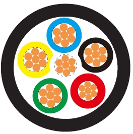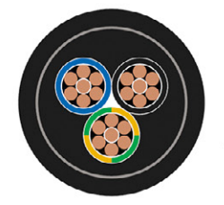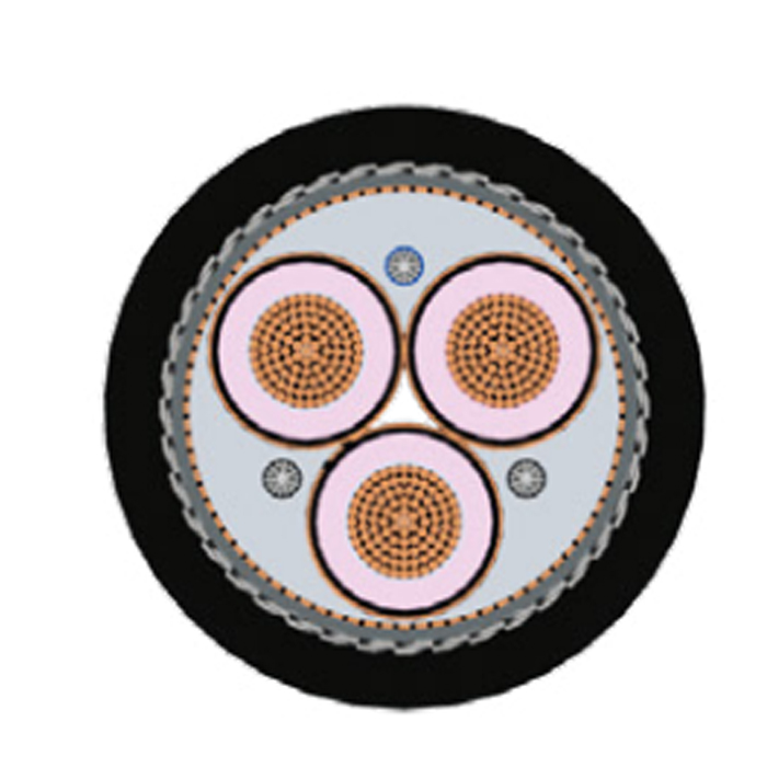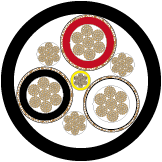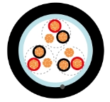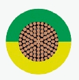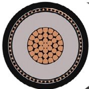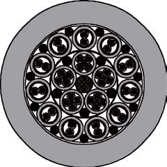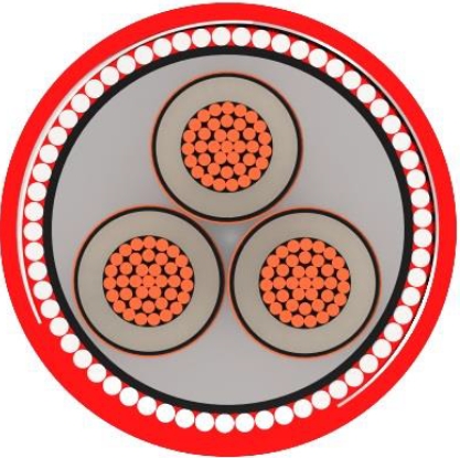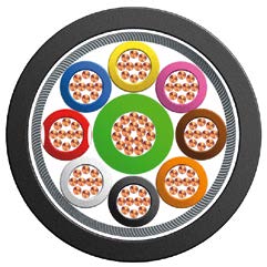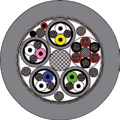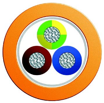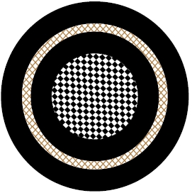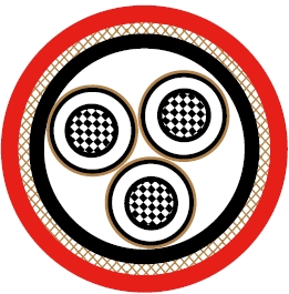
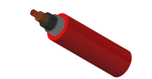
BURY CABLE single-core XLPE AWA LSZH cable combines copper conductors, XLPE insulation, aluminium wire armour and a halogen free sheath for fixed 600/1000V distribution. It serves building, industrial and infrastructure projects that specify both mechanical protection and low smoke zero halogen materials.
Choose the cable size and single-core circuit arrangement together. Armour terminations, bonding, supports and the installation environment form part of the project design.
Basic design to IEC 60502-1
| Flame Retardance (Single vertical wire or cable test) | IEC 60332-1-2; EN 60332-1-2 |
| Reduced Fire Propagation (Vertically-mounted bundled wires & cables test) | IEC 60332-3-24; EN 60332-3-24 |
| Halogen Free | IEC 60754-1; EN 50267-2-1 |
| No Corrosive Gas Emission | IEC 60754-2; EN 50267-2-2 |
| Minimum Smoke Emission | IEC 61034-2; EN 61034-2 |
600/1000V
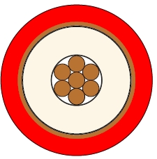
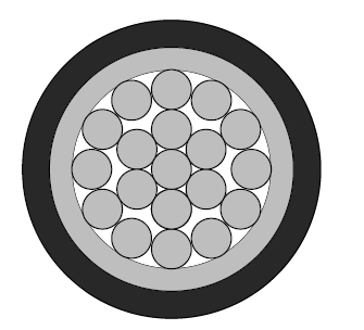
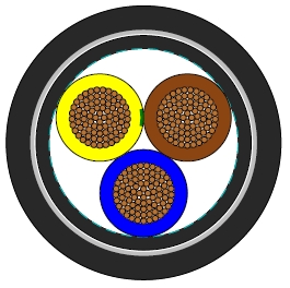
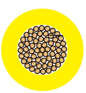
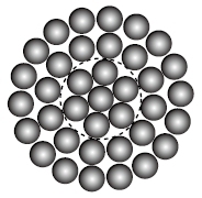
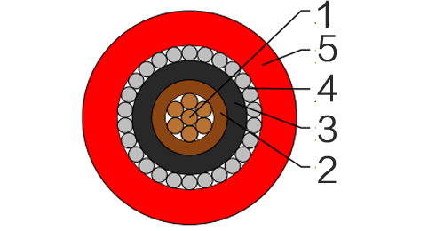
Conductor : The conductors shall be class 2 plain or metal-coated annealed copper in accordance with IEC 60228. Class 1 and class 5 conductor can be offered as option.
Insulation : Thermosetting XLPE compound as per IEC 60502-1.
Inner Covering Option : Thermoplastic halogen free compound ST8 as per IEC 60502-1.
Armouring : Aluminium wire.
Outer Sheath : Thermoplastic halogen free compound ST8 as per IEC 60502-1.
Outer Sheath Option : UV resistance, hydrocarbon resistance, oil resistance, anti-rodent and anti-termite properties can be offered as option.
Insulation Colour : Brown or blue; other colours can be offered upon request.
Sheath Colour : Black; other colours can be offered upon request.
Maximum temperature range during operation : 90°C
Maximum short circuit temperature (5 Seconds) : 250°C
Minimum bending radius : 6 × Overall Diameter
| Conductor | FLP600-RZ1MAZ1-R | ||||||
|---|---|---|---|---|---|---|---|
| No. of Cores × Cross-sectional Area | Conductor Class | Nominal Insulation Thickness | Nominal Inner Covering Thickness | Nominal AL Wire Diameter | Nominal Sheath Thickness | Approx. Overall Diameter | Approx. Weight |
| No.×mm² | mm | mm | mm | mm | mm | kg/km | |
| 1×4 | 2 | 0.7 | 1.0 | 0.8 | 1.8 | 11.2 | 200 |
| 1×6 | 2 | 0.7 | 1.0 | 0.8 | 1.8 | 11.7 | 233 |
| 1×10 | 2 | 0.7 | 1.0 | 0.8 | 1.8 | 12.7 | 294 |
| 1×16 | 2 | 0.7 | 1.0 | 0.8 | 1.8 | 13.7 | 377 |
| 1×25 | 2 | 0.9 | 1.0 | 0.8 | 1.8 | 15.4 | 513 |
| 1×35 | 2 | 0.9 | 1.0 | 1.25 | 1.8 | 17.5 | 688 |
| 1×50 | 2 | 1.0 | 1.0 | 1.25 | 1.8 | 19.0 | 856 |
| 1×70 | 2 | 1.1 | 1.0 | 1.25 | 1.8 | 21.0 | 1124 |
| 1×95 | 2 | 1.1 | 1.0 | 1.6 | 1.8 | 24.0 | 1521 |
| 1×120 | 2 | 1.2 | 1.0 | 1.6 | 1.8 | 25.8 | 1831 |
| 1×150 | 2 | 1.4 | 1.0 | 1.6 | 1.8 | 27.8 | 2176 |
| 1×185 | 2 | 1.6 | 1.0 | 1.6 | 1.8 | 30.4 | 2668 |
| 1×240 | 2 | 1.7 | 1.0 | 1.6 | 1.9 | 33.5 | 3367 |
| 1×300 | 2 | 1.8 | 1.0 | 2.0 | 2.0 | 37.5 | 4241 |
| 1×400 | 2 | 2.0 | 1.2 | 2.0 | 2.2 | 41.3 | 5283 |
| 1×500 | 2 | 2.2 | 1.2 | 2.0 | 2.3 | 45.4 | 6535 |
Conductor operating temperature : 90°C
Ambient temperature : 30°C
| Conductor cross-sectional area | Ref. Method C (clipped direct) | Ref. Method F (in free air or on a perforated cable tray, horizontal or vertical) | |||||||||
|---|---|---|---|---|---|---|---|---|---|---|---|
| Touching | Touching | Spaced by on cable diameter | |||||||||
| 2 cables, single-phase a.c. or d.c. flat | 3 or 4 cables, three-phase a.c. flat | 2 cables, single-phase a.c. or d.c. flat | 3 or 4 cables, three-phase a.c. flat | 3 cables three-phase a.c. trefoil | 2 cables, d.c. | 2 cables, single-phase a.c. | 3 or 4 cables, three-phase a.c. | ||||
| Horizontal | Vertical | Horizontal | Vertical | Horizontal | Vertical | ||||||
| 1 | 2 | 3 | 4 | 5 | 6 | 7 | 8 | 9 | 10 | 11 | 12 |
| mm² | A | A | A | A | A | A | A | A | A | A | A |
| 50 | 237 | 220 | 253 | 232 | 222 | 284 | 270 | 282 | 266 | 288 | 266 |
| 70 | 303 | 277 | 322 | 293 | 285 | 356 | 349 | 357 | 337 | 358 | 331 |
| 95 | 367 | 333 | 389 | 352 | 346 | 446 | 426 | 436 | 412 | 425 | 393 |
| 120 | 425 | 383 | 449 | 405 | 402 | 519 | 497 | 504 | 477 | 485 | 449 |
| 150 | 488 | 437 | 516 | 462 | 463 | 600 | 575 | 566 | 539 | 549 | 510 |
| 185 | 557 | 496 | 587 | 524 | 529 | 688 | 660 | 643 | 614 | 618 | 574 |
| 240 | 656 | 579 | 689 | 612 | 625 | 815 | 782 | 749 | 714 | 715 | 666 |
| 300 | 755 | 662 | 792 | 700 | 720 | 943 | 906 | 842 | 805 | 810 | 755 |
| 400 | 853 | 717 | 899 | 767 | 815 | 1137 | 1094 | 929 | 889 | 848 | 797 |
| 500 | 962 | 791 | 1016 | 851 | 918 | 1314 | 1266 | 1032 | 989 | 923 | 871 |
| Conductor cross-sectional area | 2 cables d.c. | Ref. Methods C&F (clipped direct, on trays or in free air) | ||||||||||||||
|---|---|---|---|---|---|---|---|---|---|---|---|---|---|---|---|---|
| 2 cables, single-phase a.c. | 3 or 4 cables, three-phase a.c. | |||||||||||||||
| Touching | Spaced* | Trefoil and touching | Flat and touching | Flat and spaced* | ||||||||||||
| 1 | 2 | 3 | 4 | 5 | 6 | 7 | ||||||||||
| mm² | mV/A/m | mV/A/m | mV/A/m | mV/A/m | mV/A/m | mV/A/m | ||||||||||
| r | x | z | r | x | z | r | x | z | r | x | z | r | x | z | ||
| 50 | 0.98 | 0.99 | 0.21 | 1.00 | 0.98 | 0.29 | 1.00 | 0.86 | 0.180 | 0.87 | 0.84 | 0.25 | 0.88 | 0.84 | 0.33 | 0.90 |
| 70 | 0.67 | 0.68 | 0.20 | 0.71 | 0.69 | 0.29 | 0.75 | 0.59 | 0.170 | 0.62 | 0.60 | 0.25 | 0.65 | 0.62 | 0.32 | 0.70 |
| 95 | 0.49 | 0.51 | 0.195 | 0.55 | 0.53 | 0.28 | 0.60 | 0.44 | 0.170 | 0.47 | 0.46 | 0.24 | 0.52 | 0.49 | 0.31 | 0.58 |
| 120 | 0.39 | 0.41 | 0.190 | 0.45 | 0.43 | 0.27 | 0.51 | 0.35 | 0.165 | 0.39 | 0.38 | 0.34 | 0.44 | 0.41 | 0.30 | 0.51 |
| 150 | 0.31 | 0.33 | 0.185 | 0.38 | 0.36 | 0.27 | 0.45 | 0.29 | 0.160 | 0.33 | 0.31 | 0.23 | 0.39 | 0.34 | 0.39 | 0.45 |
| 185 | 0.25 | 0.27 | 0.185 | 0.33 | 0.30 | 0.26 | 0.40 | 0.23 | 0.160 | 0.28 | 0.26 | 0.23 | 0.34 | 0.29 | 0.29 | 0.41 |
| 240 | 0.195 | 0.21 | 0.180 | 0.28 | 0.24 | 0.26 | 0.35 | 0.180 | 0.155 | 0.24 | 0.21 | 0.22 | 0.30 | 0.24 | 0.28 | 0.37 |
| 300 | 0.155 | 0.17 | 0.175 | 0.25 | 0.195 | 0.25 | 0.32 | 0.145 | 0.150 | 0.21 | 0.170 | 0.22 | 0.28 | 0.20 | 0.27 | 0.34 |
| 400 | 0.115 | 0.145 | 0.170 | 0.22 | 0.180 | 0.24 | 0.30 | 0.125 | 0.150 | 0.195 | 0.160 | 0.21 | 0.27 | 0.20 | 0.27 | 0.33 |
| 500 | 0.093 | 0.125 | 0.170 | 0.21 | 0.165 | 0.24 | 0.29 | 0.105 | 0.145 | 0.180 | 0.145 | 0.20 | 0.25 | 0.190 | 0.24 | 0.31 |
Note : *Spacings larger than one cable diameter will result in a large voltage drop.
r = conductor resistance at operating temperature
x = reactance
z = impedance
16 Class 2 copper sizes from 4 to 500 mm².
Aluminium wire armour with ST8 halogen free outer sheath.
90°C maximum operating temperature; 250°C short circuit for 5 seconds.
Minimum bending radius: 6 times the overall diameter.
Current-rating and voltage-drop data distinguish flat, trefoil, touching and spaced arrangements.
Use AWA glands and terminations appropriate to the selected dimensions and project bonding design.
The electrical tables cite BS 7671:2008 with 90°C conductor and 30°C ambient conditions. Confirm corrections and applicable project requirements.
The construction table covers 4–500 mm²; obtain project electrical data for sizes not covered by the electrical table.
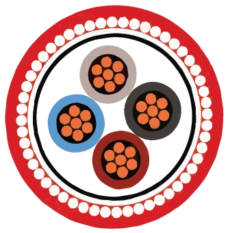
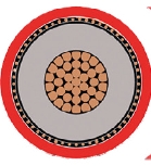
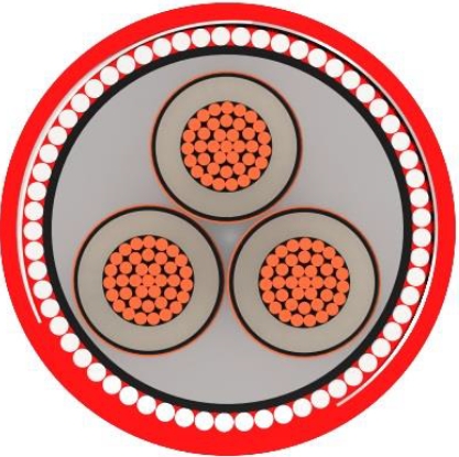
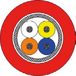
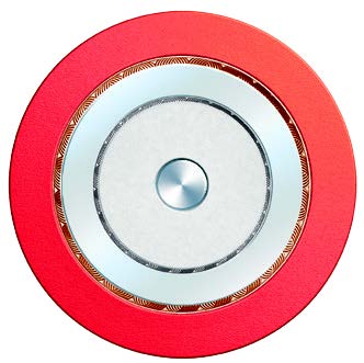
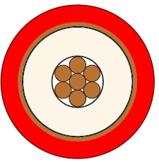
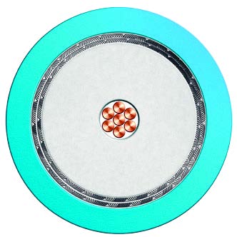
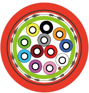
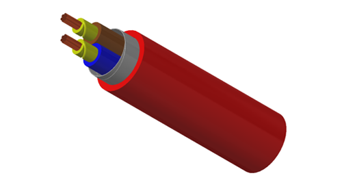
Confirm the required inner covering, sheath colour and optional environmental properties. The red sheath in the illustration is a colour reference.
This single-core construction uses aluminium wire armour. The related multicore LSZH armoured product uses steel wire armour.
The stated standard sheath colour is black; other colours are available on request. Confirm the colour when ordering.
Choose flat or trefoil formation, spacing and bonding to suit the circuit design and the relevant electrical data.
Smoke and halogen performance do not establish fire survival. Ask BURY CABLE for a cable with the specified circuit-integrity evidence where required.
Send size, run lengths, current and fault duty, route conditions, armour termination needs, sheath options and project specifications.