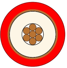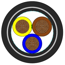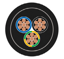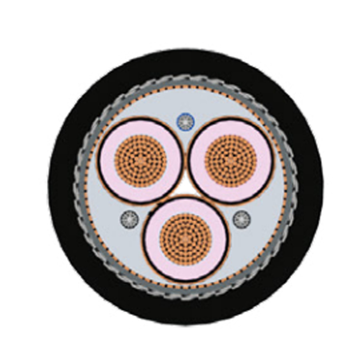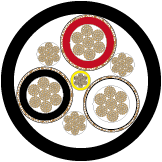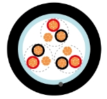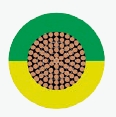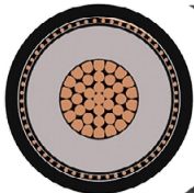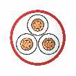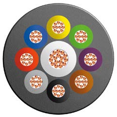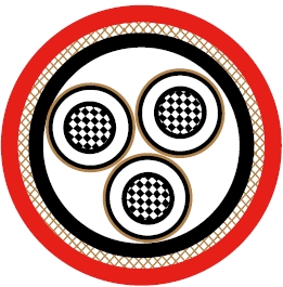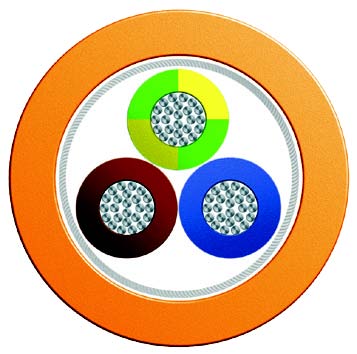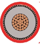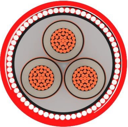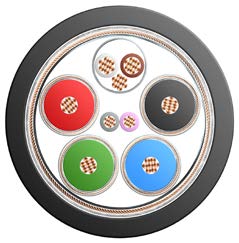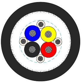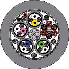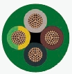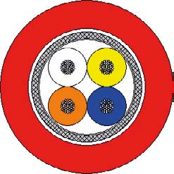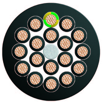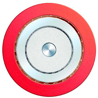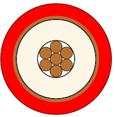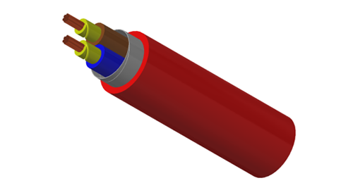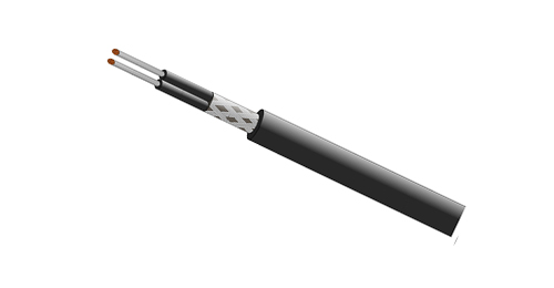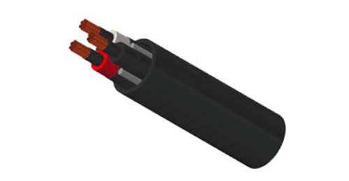
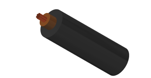
BURY CABLE single-core copper XLPE PVC cable is designed for fixed 600/1000V distribution in buildings, industrial plants and utility installations. XLPE insulation and a PVC outer sheath provide a compact unarmoured construction for protected cable routes.
Select conductor size, circuit formation and sheath grade for the installation. Conduit, trunking and trays should provide the support and protection required by the project design.
Basic design to to IEC 60502-1
| Flame Retardance (Single Vertical Wire Test) | IEC 60332-1-2 |
600/1000V
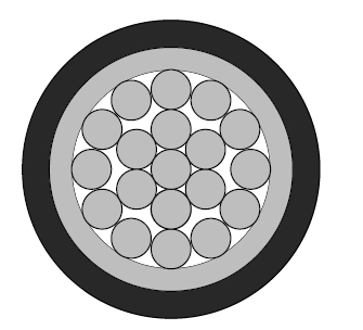
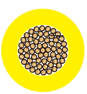
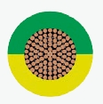
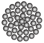
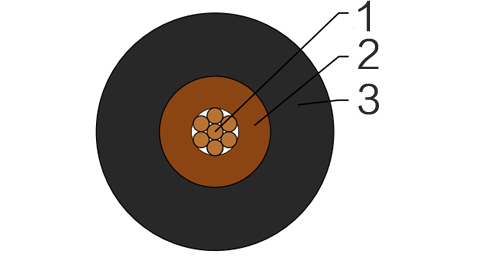
| Conductor | Plain annealed copper, stranded according to IEC 60228 class 2. |
| Insulation | XLPE according to IEC 60502-1. |
| Outer Sheath | Extruded PVC Type ST1/ST2 according to IEC 60502-1. |
| Outer Sheath Option | UV resistance, hydrocarbon resistance, oil resistance, anti rodent and anti termite properties can be offered as option. Compliance to fire performance standard (IEC 60332-1, IEC 60332-3, UL 1581, UL 1666 etc) depends on the oxygen index of the PVC compound and the overall cable design. LSPVC can also be provided upon request. |
| Insulation Colour | Brown or blue, other colours can be offered upon request. |
| Sheath Colour | Black, other colours can be offered upon request. |
| Maximum temperature range during operation | 80°C (For ST1 Sheath); 90°C (For ST2 Sheath) | |
| Maximum short circuit temperature (5 Seconds) | 250°C | |
| Minimum bending radius | ||
| Circular copper conductor (OD ≤ 25mm)4 x Overall Diameter Circular copper conductor (OD > 25mm)6 x Overall Diameter Shaped copper conductor8 x Overall Diameter | ||
| Conductor | FLP600-RV-R | ||||
|---|---|---|---|---|---|
| No. of Cores x Cross Section | Class of Conductor | Nominal Insulation Thickness | Nominal Sheath Thickness | Nominal Overall Diameter | Approx. Weight |
| No.xmm2 | mm | mm | mm | kg/km | |
| 1x1.5 | 2 | 0.7 | 1.4 | 6.1 | 36 |
| 1x2.5 | 2 | 0.7 | 1.4 | 6.8 | 52 |
| 1x4.0 | 2 | 0.7 | 1.4 | 7.4 | 76 |
| 1x6.0 | 2 | 0.7 | 1.4 | 8.2 | 100 |
| 1x10 | 2 | 0.7 | 1.4 | 9.2 | 160 |
| 1x16 | 2 | 0.7 | 1.4 | 10.7 | 230 |
| 1x25 | 2 | 0.9 | 1.4 | 12.5 | 340 |
| 1x35 | 2 | 0.9 | 1.4 | 13.5 | 440 |
| 1x50 | 2 | 1 | 1.4 | 13.7 | 541 |
| 1x70 | 2 | 1.1 | 1.4 | 15.8 | 749 |
| 1x95 | 2 | 1.1 | 1.5 | 17.5 | 1000 |
| 1x120 | 2 | 1.2 | 1.5 | 19.3 | 1241 |
| 1x150 | 2 | 1.4 | 1.6 | 21.5 | 1523 |
| 1x185 | 2 | 1.6 | 1.6 | 24.7 | 1942 |
| 1x240 | 2 | 1.7 | 1.7 | 27.7 | 2514 |
| 1x300 | 2 | 1.8 | 1.8 | 30.6 | 3125 |
| 1x400 | 2 | 2 | 1.9 | 34.2 | 3967 |
| 1x500 | 2 | 2.2 | 2 | 38 | 5063 |
| 1x630 | 2 | 2.4 | 2.2 | 42.9 | 6491 |
| 1x800 | 2 | 2.6 | 2.3 | 46 | 8075 |
| 1x1000 | 2 | 2.8 | 2.4 | 63 | 9860 |
| Conductor Operating Temperature | 70°C |
| Ambient Temperature | 30°C |
| Conductor cross-sectional area | Reference Method A (enclosed in conduit in thermally insulating wall etc) | Reference Method B (enclosed in conduit on a wall or in trunking etc) | Reference Method C (clipped direct) | Reference Method F (in free air or on a perforated cable tray horizontal or vertical etc) | Reference Method G (in free air) Spaced by one cable diameter | |||||||
|---|---|---|---|---|---|---|---|---|---|---|---|---|
| 2 cables, single-phase a.c. or d.c. | 3 or 4 cables, three-phase a.c. | 2 cables, single-phase a.c. or d.c | 3 or 4 cables, three-phase a.c. | 2 cables, single-phase a.c. or d.c. flat and touching | 3 or 4 cables, three-phase a.c. flat and touching or trefoil | 2 cables, single-phase a.c. or d.c. flat | 3 cables, three-phase a.c. flat | 3 cables, three-phase a.c. trefoil | 2 cables, single-phase a.c. or d.c. or 3 cables three-phase a.c. flat | |||
| Horizontal | Vertical | |||||||||||
| 1 | 2 | 3 | 4 | 5 | 6 | 7 | 8 | 9 | 10 | 11 | 12 | |
| mm² | A | A | A | A | A | A | A | A | A | A | A | |
| 1.5 | 19 | 17 | 23 | 20 | 25 | 23 | - | - | - | - | - | |
| 2.5 | 26 | 23 | 31 | 28 | 34 | 31 | - | - | - | - | - | |
| 4 | 35 | 31 | 42 | 37 | 46 | 41 | - | - | - | - | - | |
| 6 | 45 | 40 | 54 | 48 | 59 | 54 | - | - | - | - | - | |
| 10 | 61 | 54 | 75 | 66 | 81 | 74 | - | - | - | - | - | |
| 16 | 81 | 73 | 100 | 88 | 109 | 99 | - | - | - | - | - | |
| 25 | 106 | 95 | 133 | 117 | 143 | 130 | 161 | 141 | 135 | 182 | 161 | |
| 35 | 131 | 117 | 164 | 144 | 176 | 161 | 200 | 176 | 169 | 226 | 201 | |
| 50 | 158 | 141 | 198 | 175 | 228 | 209 | 242 | 216 | 207 | 275 | 246 | |
| 70 | 200 | 179 | 253 | 222 | 293 | 268 | 310 | 279 | 268 | 353 | 318 | |
| 95 | 241 | 216 | 306 | 269 | 355 | 326 | 377 | 342 | 328 | 430 | 389 | |
| 120 | 278 | 249 | 354 | 312 | 413 | 379 | 437 | 400 | 383 | 500 | 454 | |
| 150 | 318 | 285 | 393 | 342 | 476 | 436 | 504 | 464 | 444 | 577 | 527 | |
| 185 | 362 | 324 | 449 | 384 | 545 | 500 | 575 | 533 | 510 | 661 | 605 | |
| 240 | 424 | 380 | 528 | 450 | 644 | 590 | 679 | 634 | 607 | 781 | 719 | |
| 300 | 486 | 435 | 603 | 514 | 743 | 681 | 783 | 736 | 703 | 902 | 833 | |
| 400 | - | - | 683 | 584 | 868 | 793 | 940 | 868 | 823 | 1085 | 1008 | |
| 500 | - | - | 783 | 666 | 990 | 904 | 1083 | 998 | 946 | 1253 | 1169 | |
| 630 | - | - | 900 | 764 | 113 | 1033 | 1254 | 1151 | 1088 | 1454 | 1362 | |
| 800 | - | - | - | - | 1288 | 1179 | 1358 | 1275 | 1214 | 1581 | 1485 | |
| 1000 | - | - | - | - | 1443 | 1323 | 1520 | 1436 | 1349 | 1775 | 1671 | |
| Nominal Cross Section Area | 2 cables d.c. | 2 cables, single-phase a.c. | 3 or 4 cables, three-phase a.c. | ||||||||||||||||
|---|---|---|---|---|---|---|---|---|---|---|---|---|---|---|---|---|---|---|---|
| Ref. Methods A and B (enclosed in conduit or trunking) | Ref. Methods C, F & G(clipped direct, on trays or in free air) | Ref. Methods A & B (enclosed in conduit or trunking | Ref. Methods C, F & G (clipped direct, on trays or in free air) | ||||||||||||||||
| 1 | 2 | 3 | Cables touching 4 | Cables spaced* 5 | 6 | 7 | |||||||||||||
| mm² | mV/A/m | mV/A/m | mV/A/m | mV/A/m | mV/A/m | mV/A/m | |||||||||||||
| 1.5 | 31 | 31 | 27 | 27 | 27 | 27 | |||||||||||||
| 2.5 | 19 | 19 | 16 | 16 | 16 | 16 | |||||||||||||
| 4 | 33 | 12 | 10 | 10 | 10 | 10 | |||||||||||||
| 6 | 7.8 | 7.9 | 6.8 | 6.8 | 6.8 | 6.8 | |||||||||||||
| 10 | 4.7 | 4.7 | 4.7 | 4 | 4 | 4 | |||||||||||||
| 16 | 2.9 | 2.9 | 2.9 | 2.5 | 2.5 | 2.5 | |||||||||||||
| r | x | z | r | x | z | r | x | z | r | x | z | r | x | z | |||||
| 25 | 1.85 | 1.6 | 0.31 | 1.9 | 1.85 | 0.19 | 1.85 | 1.6 | 0.27 | 1.65 | 1.6 | 0.165 | 1.6 | 1.6 | 0.19 | 1.6 | |||
| 35 | 1.35 | 1.35 | 0.29 | 1.35 | 1.35 | 0.18 | 1.35 | 1.15 | 0.25 | 1.15 | 1.15 | 0.155 | 1.5 | 1.15 | 0.18 | 1.15 | |||
| 50 | 0.99 | 1 | 0.29 | 1.05 | 0.99 | 0.18 | 1 | 0.87 | 0.25 | 0.9 | 0.86 | 0.155 | 0.87 | 0.86 | 0.18 | 0.87 | |||
| 70 | 0.68 | 0.7 | 0.28 | 0.75 | 0.68 | 0.175 | 0.71 | 0.6 | 0.24 | 0.65 | 0.59 | 0.15 | 0.61 | 0.59 | 0.175 | 0.62 | |||
| 95 | 0.49 | 0.51 | 0.27 | 0.58 | 0.49 | 0.17 | 0.52 | 0.44 | 0.23 | 0.5 | 0.43 | 0.145 | 0.45 | 0.43 | 0.17 | 0.46 | |||
| 120 | 0.39 | 0.41 | 0.26 | 0.48 | 0.39 | 0.165 | 0.43 | 0.35 | 0.23 | 0.42 | 0.34 | 0.14 | 0.37 | 0.34 | 0.165 | 0.38 | |||
| 150 | 0.32 | 0.33 | 0.26 | 0.43 | 0.32 | 0.165 | 0.36 | 0.29 | 0.23 | 0.37 | 0.28 | 0.14 | 0.31 | 0.28 | 0.165 | 0.32 | |||
| 185 | 0.25 | 0.27 | 0.26 | 0.37 | 0.26 | 0.165 | 0.3 | 0.23 | 0.23 | 0.32 | 0.22 | 0.14 | 0.26 | 0.22 | 0.165 | 0.28 | |||
| 240 | 0.19 | 0.21 | 0.26 | 0.33 | 0.2 | 0.16 | 0.25 | 0.185 | 0.22 | 0.29 | 0.17 | 0.14 | 0.22 | 0.17 | 0.165 | 0.24 | |||
| 300 | 0.155 | 0.175 | 0.25 | 0.31 | 0.16 | 0.16 | 0.22 | 0.15 | 0.22 | 0.27 | 0.14 | 0.14 | 0.195 | 0.135 | 0.16 | 0.21 | |||
| 400 | 0.12 | 0.14 | 0.25 | 0.29 | 0.13 | 0.155 | 0.2 | 0.125 | 0.22 | 0.25 | 0.11 | 0.135 | 0.175 | 0.11 | 0.16 | 0.195 | |||
| 500 | 0.093 | 0.12 | 0.25 | 0.28 | 0.105 | 0.155 | 0.185 | 0.1 | 0.22 | 0.24 | 0.09 | 0.135 | 0.16 | 0.088 | 0.16 | 0.18 | |||
| 630 | 0.072 | 0.1 | 0.25 | 0.27 | 0.086 | 0.155 | 0.175 | 0.088 | 0.21 | 0.23 | 0.074 | 0.135 | 0.15 | 0.071 | 0.16 | 0.17 | |||
| 800 | 0.056 | - | - | - | 0.072 | 0.15 | 0.17 | - | - | - | 0.062 | 0.13 | 0.145 | 0.059 | 0.155 | 0.165 | |||
| 1000 | 0.045 | - | - | - | 0.063 | 0.15 | 0.165 | - | - | - | 0.055 | 0.13 | 0.14 | 0.05 | 0.155 | 0.165 | |||
Note: *Spacings larger than one cable diameter will result in a large voltage drop.
r = conductor resistance at operating temperature
x = reactance
z = impedance
21 Class 2 copper sizes from 1.5 to 1000 mm².
XLPE insulation and PVC ST1/ST2 sheath options.
Listed operating limits: 80°C with ST1 sheath or 90°C with ST2 sheath.
Short-circuit limit: 250°C for 5 seconds.
Construction dimensions plus installation-specific electrical reference tables.
Confirm sheath grade, operating temperature and project current-rating data with BURY CABLE before final selection.
The electrical tables carry BS 7671:2008 references. Match the final rating to the approved temperature basis, installation method, formation and grouping.
Check the bending rule for circular conductors up to or above 25 mm diameter, or the shaped conductor rule.
Specify core and sheath colours and any UV, oil, hydrocarbon or pest protection. Request LSZH construction separately if required.
This product has no metallic armour. For an armoured single-core circuit, compare the related AWA PVC construction.
The listed ST1 limit is 80°C and ST2 limit is 90°C. Confirm the supplied sheath and complete installation rating.
PVC is a halogen-containing material. If halogen free performance is required, select a suitable LSZH construction.
Final sizing also depends on route conditions, grouping, voltage drop, fault duty and equipment terminations; request matched project data.
Send area, quantity, length per run, operating temperature, route conditions, sheath grade, colours and project specification.