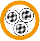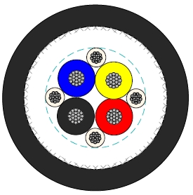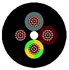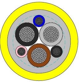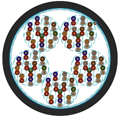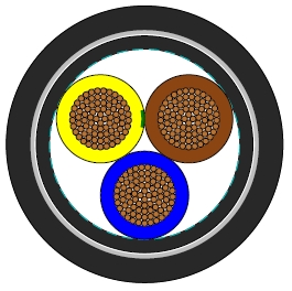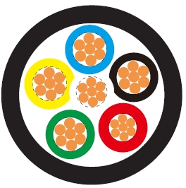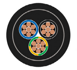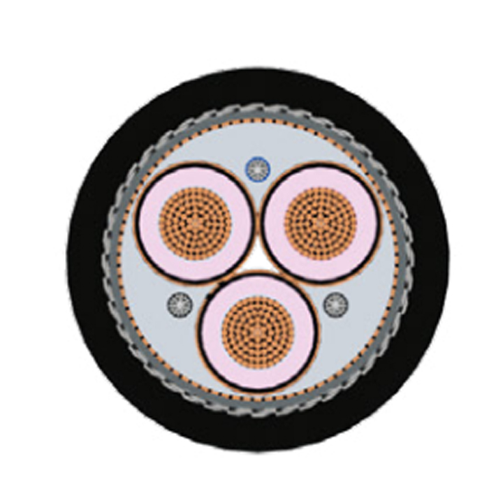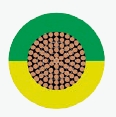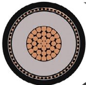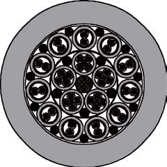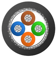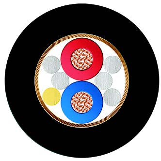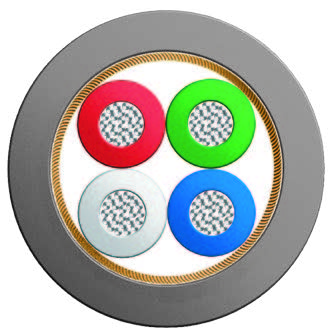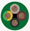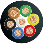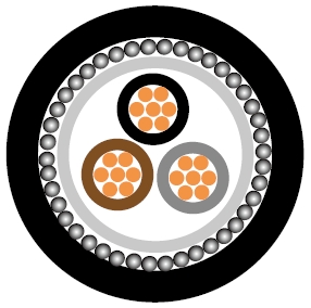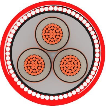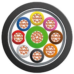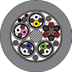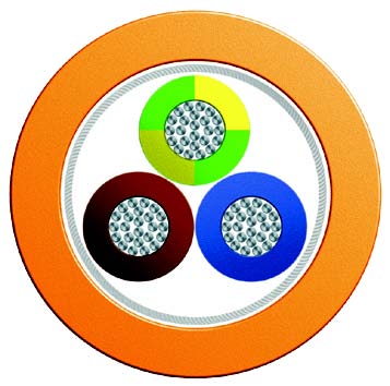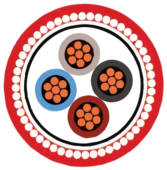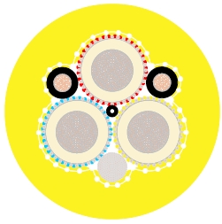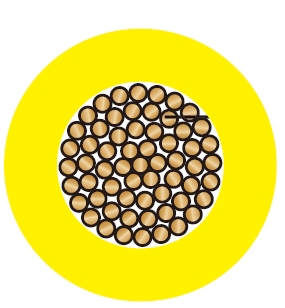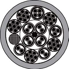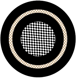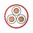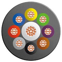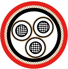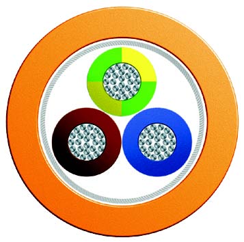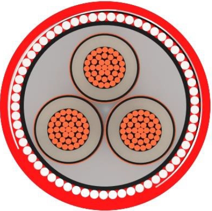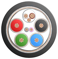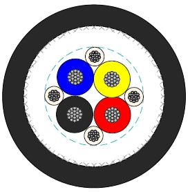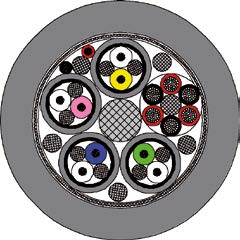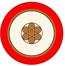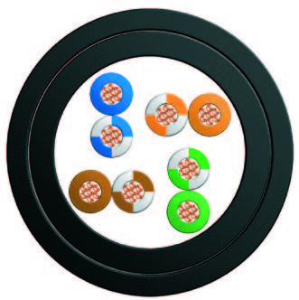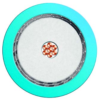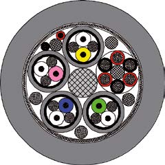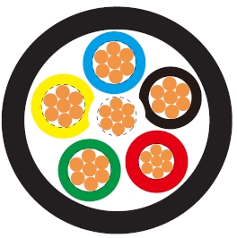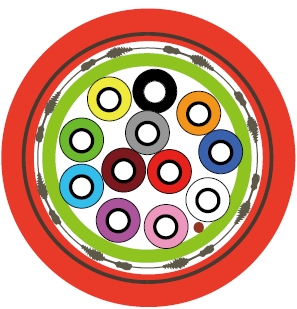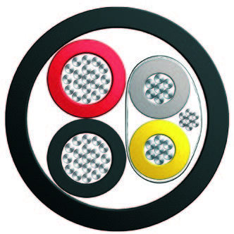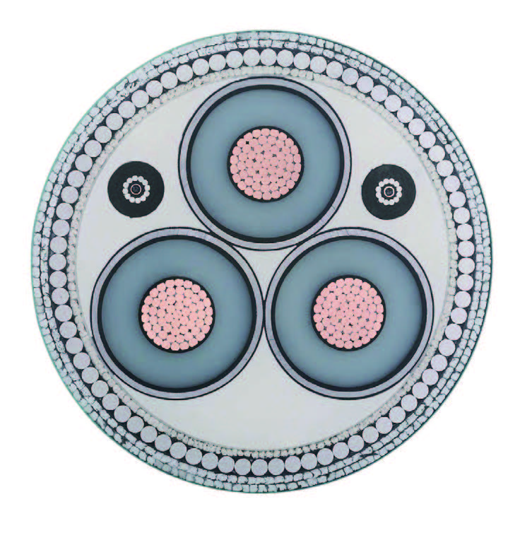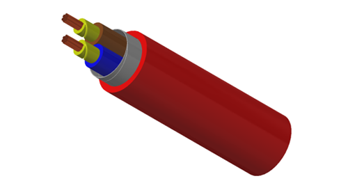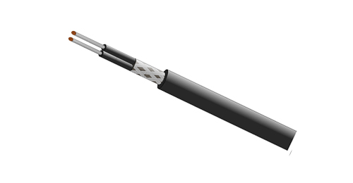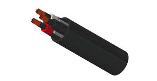
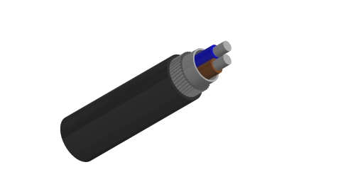
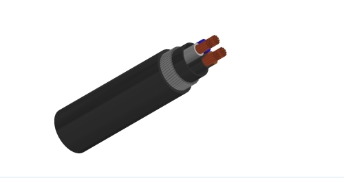
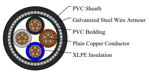
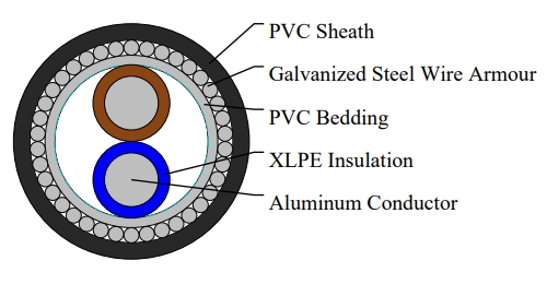
BURY CABLE EEMUA 133 600/1000V lead covered armoured cables are designed for fixed power and control circuits in refineries, petrochemical plants, chemical facilities and industrial infrastructure. The copper conductor construction combines XLPE insulation, a lead alloy sheath, PVC layers and wire armour.
The lead covering provides an additional environmental barrier where exposure to hydrocarbons, solvents or moisture is a project concern. Wire armour provides mechanical protection along fixed cable routes. Share the expected chemicals, temperatures and site conditions with BURY CABLE so the sheath specification can be matched to the application.
Installation routes include trays, ducts, trenches and underground systems, subject to the approved project design. The range below includes single-core power cables, two-, three- and four-core cables, and multicore control configurations.
| Conductor | Annealed Copper conductor, circular or shaped, Class 2 to BS EN60228. |
| Insulation | XLPE (Cross-Linked Polyethylene) Type GP 8 conforming to BS 7655-1.3 or type GP 6 conforming to BS 7655-1.2. |
| Colour Code | 1 Core : Brown or Blue |
| 2 Cores : Brown, Blue | |
| 3 Cores : Brown, Black, Grey | |
| 4 Cores : Blue, Brown, Black, Grey | |
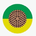
| 5 Cores : Green/Yellow, Blue, Brown, Black, Grey | |
| Above 5 Cores : White Cores with black numerals | |
| Bedding | PVC (Polyvinyl Chloride) |
| Protection | LC (Lead alloy 'E') sheathed |
| Inner Sheath | PVC (Polyvinyl Chloride) |
| Armour | Single Core : AWA (Aluminum Wire Armour) |
| Multi Core : GSWA (Galvanized Steel Wire Armour) | |
| Outer Sheath | PVC(Polyvinyl Chloride), or anti-rodent and anti-termite PVC(optional) |
| Voltage rating | 600/1000V |
| Temperature rating | 0°C to +90°C |
| Bending radius | 12 x overall diameter |
| Flame retardant | BS EN 60332-1-2 |
| Nominal Cross-sectional Area | Strand Type | Nominal Insulation thickness | Nominal Lead sheath thickness | Nominal Inner Sheath thickness | Nominal Alum wire Armor dia. | Nominal Outer Sheath thickness | Approx. Overall Diameter | Aprrox Weight |
|---|---|---|---|---|---|---|---|---|
| mm² | No./mm | mm | mm | mm | mm | mm | mm | kg/km |
| 1x50 | 19/1.78 | 1 | 1.2 | 0.8 | 1.37 | 1.5 | 20 | 1285 |
| 1x70 | 19/2.14 | 1.1 | 1.2 | 0.8 | 1.37 | 1.5 | 22 | 1605 |
| 1x95 | 19/2.52 | 1.1 | 1.2 | 0.8 | 1.37 | 1.6 | 24 | 1965 |
| 1x120 | 37/2.03 | 1.2 | 1.3 | 0.8 | 1.37 | 1.6 | 25.5 | 2365 |
| 1x150 | 37/2.25 | 1.4 | 1.3 | 1 | 1.37 | 1.7 | 28 | 2800 |
| 1x185 | 37/2.52 | 1.6 | 1.4 | 1 | 1.72 | 1.8 | 31 | 3490 |
| 1x240 | 61/2.25 | 1.7 | 1.5 | 1 | 1.72 | 1.8 | 34 | 4300 |
| 1x300 | 61/2.52 | 1.8 | 1.6 | 1 | 1.72 | 1.9 | 37 | 5203 |
| 1x400 | 61/2.85 | 2 | 1.7 | 1.2 | 2.14 | 2 | 42 | 6615 |
| Nominal Cross-sectional Area | Strand Type | Nominal Insulation thick-ness | Nominal Lead sheath thickness | Nominal Inner Sheath thickness | Nominal Steel Wire Armor dia. | Nominal Outer Sheath thickness | Approx. Overall Diameter | Aprrox Weight |
|---|---|---|---|---|---|---|---|---|
| mm² | No./mm | mm | mm | mm | mm | mm | mm | kg/km |
| 2x1.5 | 7/0.53 | 0.6 | 1.2 | 0.8 | 0.9 | 1.3 | 16.5 | 780 |
| 2x2.5 | 7/0.67 | 0.7 | 1.2 | 0.8 | 0.9 | 1.4 | 17.2 | 985 |
| 2x4 | 7/0.85 | 0.7 | 1.2 | 0.8 | 0.9 | 1.4 | 18.4 | 1100 |
| 2x6 | 7/1.04 | 0.7 | 1.2 | 0.8 | 0.9 | 1.4 | 19.6 | 1240 |
| 2x10 | 7/1.35 | 0.7 | 1.2 | 0.8 | 0.9 | 1.5 | 20.8 | 1430 |
| 2x16 | 7/1.70 | 0.7 | 1.2 | 0.8 | 1.25 | 1.5 | 21.8 | 1700 |
| 2x25 | 7/2.14 | 0.9 | 1.2 | 0.8 | 1.25 | 1.6 | 25.5 | 2060 |
| 2x35* | 7/2.52 | 0.9 | 1.3 | 1 | 1.6 | 1.7 | 29.4 | 2670 |
| 2x50* | 19/1.78 | 1.0 | 1.2 | 1 | 1.6 | 1.8 | 27.2 | 2640 |
| 2x70* | 19/2.14 | 1.1 | 1.3 | 1 | 1.6 | 1.9 | 30.5 | 3400 |
| 2x95* | 19/2.52 | 1.1 | 1.4 | 1.2 | 2.0 | 2.0 | 34.5 | 4530 |
| 2x120* | 37/2.03 | 1.2 | 1.4 | 1.2 | 2.0 | 2.1 | 37.8 | 5170 |
| 2x150* | 37/2.25 | 1.4 | 1.5 | 1.2 | 2.0 | 2.2 | 41.1 | 6120 |
| 2x185* | 37/2.52 | 1.6 | 1.6 | 1.4 | 2.5 | 2.4 | 46.3 | 7710 |
| 2x240* | 61/2.25 | 1.7 | 1.8 | 1.4 | 2.5 | 2.5 | 51.7 | 9650 |
| 2x300* | 61/2.52 | 1.8 | 1.9 | 1.6 | 2.5 | 2.6 | 56.3 | 11510 |
* D-shaped stranded conductor
| Nominal Cross-sectional Area | Strand Type | Nominal Insulation thickness | Nominal Lead sheath thickness | Nominal Inner Sheath thickness | Nominal Steel Wire Armor dia. | Nominal Outer Sheath thickness | Approx. Overall Diameter | Aprrox Weight |
|---|---|---|---|---|---|---|---|---|
| mm² | No./mm | mm | mm | mm | mm | mm | mm | kg/km |
| 3x1.5 | 7/0.53 | 0.7 | 1.2 | 0.8 | 0.9 | 1.3 | 17 | 945 |
| 3x2.5 | 7/0.67 | 0.7 | 1.2 | 0.8 | 1.25 | 1.4 | 19 | 1160 |
| 3x4 | 7/0.85 | 0.7 | 1.2 | 0.8 | 1.25 | 1.4 | 20.5 | 1325 |
| 3x6 | 7/1.04 | 0.7 | 1.2 | 0.8 | 1.25 | 1.4 | 21.5 | 1490 |
| 3x10 | 7/1.35 | 0.7 | 1.2 | 0.8 | 1.25 | 1.5 | 23 | 1750 |
| 3x16 | 7/1.70 | 0.7 | 1.2 | 0.8 | 1.6 | 1.6 | 26.5 | 2150 |
| 3x25 | 7/2.14 | 0.9 | 1.3 | 1 | 1.6 | 1.7 | 31 | 3175 |
| 3x35 | 7/2.52 | 0.9 | 1.3 | 1 | 1.6 | 1.8 | 33 | 3500 |
| 3x50* | 19/1.78 | 1 | 1.4 | 1 | 1.6 | 1.8 | 33.5 | 3905 |
| 3x70* | 19/2.14 | 1.1 | 1.5 | 1 | 2 | 1.9 | 37.5 | 5195 |
| 3x95* | 19/2.52 | 1.1 | 1.5 | 1.2 | 2 | 2.1 | 41.5 | 6365 |
| 3x120* | 37/2.03 | 1.2 | 1.6 | 1.2 | 2.5 | 2.2 | 45.5 | 7935 |
| 3x150* | 37/2.25 | 1.4 | 1.8 | 1.4 | 2.5 | 2.3 | 50.5 | 9645 |
| 3x185* | 37/2.52 | 1.6 | 1.9 | 1.4 | 3.15 | 2.4 | 56.5 | 12195 |
| 3x240* | 61/2.25 | 1.7 | 2 | 1.4 | 3.15 | 2.6 | 62 | 14765 |
| 3x300* | 61/2.52 | 1.8 | 2.2 | 1.6 | 3.5 | 2.7 | 68.5 | 18300 |
* Shaped stranded conductor
| Nominal Cross-sectional Area | Strand Type | Nominal Insulation thickness | Nominal Lead sheath thickness | Nominal Inner Sheath thickness | Nominal Steel Wire Armor dia. | Nominal Outer Sheath thickness | Approx. Overall Diameter | Aprrox Weight |
|---|---|---|---|---|---|---|---|---|
| mm² | No./mm | mm | mm | mm | mm | mm | mm | kg/km |
| 4x1.5 | 7/0.53 | 0.7 | 1.2 | 0.8 | 1.25 | 1.4 | 19 | 1140 |
| 4x2.5 | 7/0.67 | 0.7 | 1.2 | 0.8 | 1.25 | 1.4 | 20 | 1270 |
| 4x4 | 7/0.85 | 0.7 | 1.2 | 0.8 | 1.25 | 1.4 | 21.5 | 1455 |
| 4x6 | 7/1.04 | 0.7 | 1.2 | 0.8 | 1.25 | 1.5 | 22.5 | 1650 |
| 4x10 | 7/1.35 | 0.7 | 1.2 | 0.8 | 1.6 | 1.5 | 25 | 2130 |
| 4x16 | 7/1.70 | 0.7 | 1.2 | 0.8 | 1.6 | 1.6 | 28 | 2640 |
| 4x25 | 7/2.14 | 0.9 | 1.3 | 1 | 1.6 | 1.7 | 33 | 3635 |
| 4x35 | 7/2.52 | 0.9 | 1.5 | 1 | 2 | 1.8 | 36.5 | 4535 |
| 4x50* | 19/1.78 | 1.0 | 1.4 | 1 | 2 | 1.9 | 38 | 5000 |
| 4x70* | 19/2.14 | 1.1 | 1.6 | 1.2 | 2 | 2.1 | 42 | 6455 |
| 4x95* | 19/2.52 | 1.1 | 1.7 | 1.2 | 2.5 | 2.2 | 47.5 | 8535 |
| 4x120* | 37/2.03 | 1.2 | 1.8 | 1.4 | 2.5 | 2.3 | 52 | 10155 |
| 4x150* | 37/2.25 | 1.4 | 1.9 | 1.4 | 3.15 | 2.4 | 58.5 | 12735 |
| 4x185* | 37/2.52 | 1.6 | 2.1 | 1.4 | 3.15 | 2.6 | 63.5 | 15344 |
| 4x240* | 61/2.25 | 1.7 | 2.2 | 1.6 | 3.5 | 2.7 | 71.5 | 19382 |
| 4x300* | 61/2.52 | 1.8 | 2.4 | 1.6 | 4 | 2.9 | 78 | 21150 |
* Shaped stranded conductor
| Nominal Cross-sectional Area | Strand Type | Nominal Insulation thickness | Nominal Lead sheath thickness | Nominal Inner Sheath thickness | Nominal Steel Wire Armor dia. | Nominal Outer Sheath thickness | Approx. Overall Diameter | Aprrox Weight |
|---|---|---|---|---|---|---|---|---|
| mm² | No./mm | mm | mm | mm | mm | mm | mm | kg/km |
| 7x1.5 | 7/0.53 | 0.7 | 1.2 | 0.8 | 1.25 | 1.4 | 20.5 | 1290 |
| 12x1.5 | 7/0.53 | 0.7 | 1.2 | 0.8 | 1.6 | 1.5 | 23.5 | 1395 |
| 19x1.5 | 7/0.53 | 0.7 | 1.2 | 0.8 | 1.6 | 1.6 | 26.5 | 1720 |
| 27x1.5 | 7/0.53 | 0.7 | 1.3 | 1 | 1.6 | 1.7 | 30.5 | 1695 |
| 37x1.5 | 7/0.53 | 0.7 | 1.5 | 1 | 1.6 | 1.8 | 34 | 1960 |
| 7x2.5 | 7/0.67 | 0.7 | 1.2 | 0.8 | 1.25 | 1.4 | 21 | 1341 |
| 12x2.5 | 7/0.67 | 0.7 | 1.2 | 0.8 | 1.6 | 1.6 | 25.5 | 2070 |
| 19x2.5 | 7/0.67 | 0.7 | 1.3 | 1 | 1.6 | 1.7 | 29 | 2545 |
| 27x2.5 | 7/0.67 | 0.7 | 1.4 | 1 | 1.6 | 1.8 | 33.5 | 3205 |
| 37x2.5 | 7/0.67 | 0.7 | 1.5 | 1 | 2 | 1.8 | 37.5 | 2660 |
| 7x4 | 7/0.85 | 0.7 | 1.2 | 0.8 | 1.25 | 1.5 | 23.5 | 1605 |
| 12x4 | 7/0.85 | 0.7 | 1.3 | 1 | 1.6 | 1.6 | 28.5 | 2538 |
| 19x4 | 7/0.85 | 0.7 | 1.4 | 1 | 1.6 | 1.7 | 32.5 | 3310 |
| 27x4 | 7/0.85 | 0.7 | 1.5 | 1 | 2 | 1.9 | 38.5 | 4215 |
| 37x4 | 7/0.85 | 0.7 | 1.6 | 1.2 | 2 | 2 | 42.5 | 5440 |
600/1000V lead covered armoured construction for EEMUA 133 / BS 5467 project specifications.
Annealed copper conductors, circular or shaped, Class 2 to BS EN 60228.
XLPE insulation, PVC bedding, lead alloy E protection, PVC inner sheath and PVC outer sheath.
Aluminium wire armour (AWA) for single-core cables; galvanized steel wire armour (GSWA) for multicore cables.
72 construction entries with strand details, layer thicknesses, approximate diameters and weights.
Temperature rating 0°C to +90°C; minimum bending radius 12 times the overall diameter.
Anti-rodent and anti-termite PVC options available to suit specified project requirements.
Send BURY CABLE the voltage, core count, conductor area, quantity, length per run, drum lengths, destination and project specification for a matched quotation.
Choose the exact construction row. Starred two-core entries use D-shaped stranded conductors; starred three- and four-core entries use shaped stranded conductors.
Specify the installation route, load, grouping, ambient or ground conditions and short-circuit duty. Contact BURY CABLE for the electrical data needed for final current-rating and voltage-drop checks.
Confirm the required lead sheath, insulation grade, outer sheath properties and chemical exposure conditions in the approved project datasheet. Optional rodent or termite protection should be included in the enquiry.
Use the selected cable diameter to check glands, supports, pulling arrangements and bending space. Confirm lead sheath and armour termination and bonding requirements with the project designer.
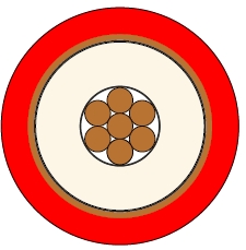
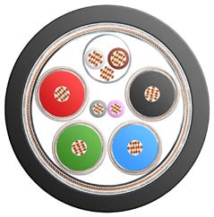
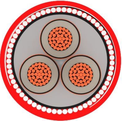
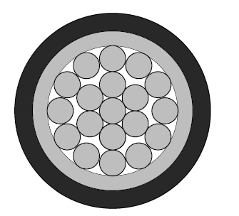
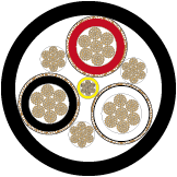
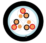
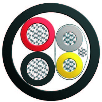
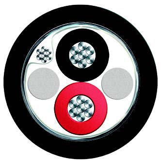
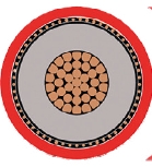
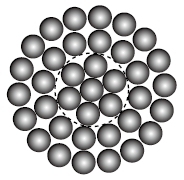
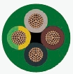
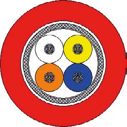
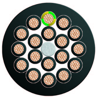
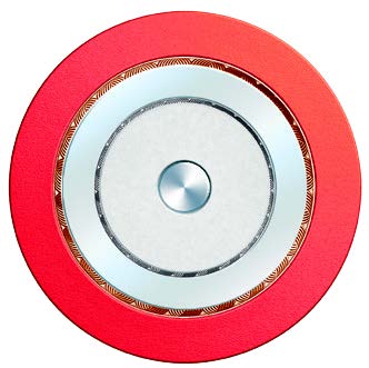
Illustrations include general cable construction references. Use the specified copper, lead-sheathed construction and the confirmed dimensions for ordering and installation.
EEMUA 133 1900/3300V three-core lead covered cable — a separate voltage range with its own dimensions.
BS 5467 600/1000V armoured power cables — compare standard armoured constructions for other fixed power routes.
BS 6724 600/1000V LSZH armoured cables — review when the project specifies low smoke zero halogen performance.
The tables cover single-core 50–400 mm², two-, three- and four-core 1.5–300 mm², plus 7, 12, 19, 27 and 37 cores in 1.5, 2.5 and 4 mm². Contact BURY CABLE for other project configurations.
The lead alloy sheath adds environmental protection where hydrocarbons, solvents or moisture are a concern. Selection should consider the actual exposure, temperature and installation conditions.
Single-core cables use aluminium wire armour. The two-, three-, four- and multicore constructions use galvanized steel wire armour. Choose the armour type with the complete circuit arrangement.
An asterisk identifies D-shaped stranded conductors in the two-core table and shaped stranded conductors in the three- and four-core tables. Use the dimensions for the marked row when selecting accessories.
Underground ducts and trenches can be considered within the approved installation design. Provide the ground conditions, route protection and chemical exposure details when requesting the cable specification.
The standard construction shown uses PVC. If LSZH is required, contact BURY CABLE to select a suitable construction and confirm its smoke and halogen performance requirements.
The technical table specifies BS EN 60332-1-2 flame retardance. For circuits required to remain operational during a fire, ask BURY CABLE for a suitable cable construction and the required circuit-integrity test evidence.
Send the voltage, core count, conductor size, lengths, installation conditions and project standards. Include lead sheath and optional outer sheath requirements, packing and delivery details. Use the attached 600/1000V PDF with the selected construction row.