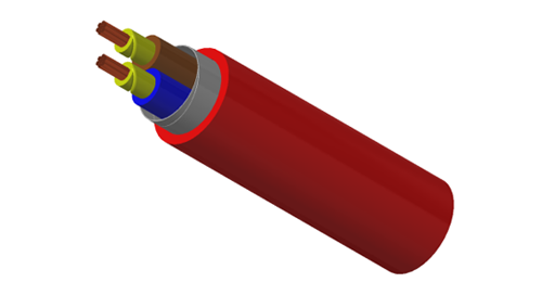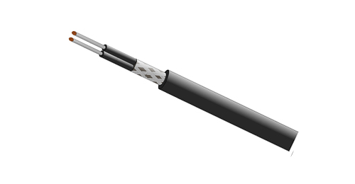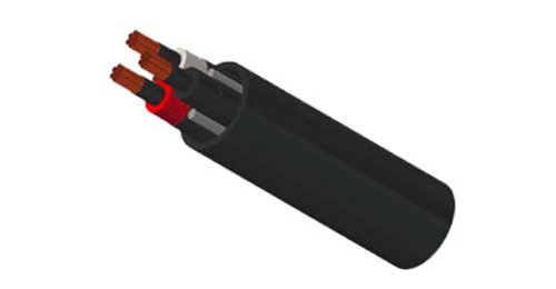
Instrumentation cable screening should match both the interference environment and the signals carried inside the cable. An overall screen surrounds the complete cable assembly; individual screens surround separate pairs or triads. Using both can improve separation between circuits while adding a common outer screening layer, but it also increases termination work and may increase cable diameter and cost.
This guide explains the differences, the meaning of PiMF, and the information engineers and purchasing teams should confirm before ordering. The terms “screen” and “shield” are used interchangeably here.
| Arrangement | Main purpose | Selection consideration |
|---|---|---|
| Overall screen | Screens the group of circuits from external electric-field interference. | Does not individually screen one pair from another. |
| Individual pair or triad screens | Separates signal groups and helps reduce coupling between them. | Confirm isolation, drain wires and the required termination scheme. |
| Individual and overall screens | Combines circuit separation with an outer screen around the assembly. | Requires more space and careful identification at terminations. |
These descriptions compare construction, not guaranteed attenuation. Actual EMC performance depends on screen material and continuity, twisting, cable geometry, frequency, routing, and how the screen connects to the equipment. A foil coverage percentage alone is not a complete measure of screening effectiveness.
An overall screened multipair cable may suit circuits with compatible signal levels and a manageable interference environment, where the equipment and project specifications permit it. The common screen provides a conductive layer around the cable bundle, but the pairs still share the space inside that layer. Evaluate coupling between circuits as well as interference from outside the cable.
Do not select this construction solely because the signal is described as 4–20 mA. Check circuit sensitivity, cable length, routing, nearby switching equipment and the requirements of the connected instruments.
Individual screening is worth considering when several sensitive circuits share one cable, when the specification requires separation between channels, or when coupling between pairs is a concern. Each screened pair or triad forms a distinct signal group. The screen and its drain wire must remain identifiable through junction boxes and marshalling cabinets.
Individual plus overall screening may be specified for demanding installations. However, adding screen layers does not correct unsuitable routing, excessive exposed conductor length or a poor connection at the enclosure. Compare the complete installed design, including glands, terminals and screen continuity.
PiMF means Pair in Metal Foil. It describes foil screening around individual pairs. The abbreviation does not, by itself, establish the overall screen, armour, voltage rating, sheath compound or fire performance. Product naming conventions vary, so confirm the construction drawing and technical data sheet rather than relying on the product code alone.
For a screened pair, the foil is commonly combined with a drain wire that provides a practical connection to the screen. Confirm drain-wire material and size, foil orientation and the manufacturer’s termination instructions. A screen drain wire must not be assumed to provide the protective earth function.
Foil can provide continuous coverage around a signal group when correctly overlapped and installed. A braid is a woven conductive screen whose coverage and electrical performance depend on its construction. A combined foil and braid arrangement may be selected when the equipment interface and EMC requirements call for it. None of these options should be chosen from coverage percentage alone.
Armour is a separate construction feature used primarily where mechanical protection is required. Its bonding and any protective-conductor role need their own engineering assessment. An armoured cable is not automatically individually screened, and a screened cable is not automatically suitable for direct burial.
There is no universal rule that every instrumentation screen must be connected at one end or at both ends. A single-end connection can be appropriate for certain low-frequency measurement circuits. At higher interference frequencies, the impedance of the connection and bonding at equipment boundaries become critical; a long drain-wire tail can compromise performance.
Bonding at both ends can allow current to flow where earth potentials differ. Follow the instrument manufacturer’s instructions, project earthing design and equipotential-bonding provisions. Keep screen connections short where required, preserve the intended isolation between individual screens, and follow the approved design for intrinsically safe circuits.
Screen construction is only one part of cable selection. Verify conductor resistance, capacitance, voltage rating and temperature range against the circuit requirements. For RTDs, check the required conductor count and resistance balance. For thermocouples, confirm the correct extension or compensating cable type and polarity; ordinary copper instrumentation cable is not a general substitute.
For RS485 or another data interface, confirm characteristic impedance, capacitance, attenuation and the equipment’s permitted cable length and data rate. A cable described as “shielded instrumentation cable” is not automatically suitable for a particular communication protocol.
| Specify in the enquiry | What to make explicit |
|---|---|
| Signal and circuit grouping | Application, number of pairs or triads, spare groups and conductor size. |
| Screen construction | Overall only, individually screened, or individual plus overall; screen and drain-wire materials. |
| Installation conditions | Tray, duct or burial; indoor or outdoor; moisture, chemicals, UV and mechanical exposure. |
| Cable requirements | Voltage and temperature ratings, insulation, sheath, armour and relevant electrical limits. |
| Standards and fire performance | Exact product standard and edition; separately stated flame, smoke, halogen or circuit-integrity requirements. |
| Inspection and delivery | Approved drawing, data sheet, required tests, identification, drum lengths and total quantity. |
Write “8 pairs × 2 conductors × 1.0 mm²” when that is the required construction. “8 cores” is not equivalent. Ask the supplier to state the overall diameter and minimum bending radius so that gland selection, tray space and installation access can be checked.
Where BS EN 50288-7 is specified, identify it explicitly and confirm the proposed construction and test requirements. Do not treat a product-standard reference as proof of every required fire property. Likewise, LSZH describes material-related characteristics; it does not, by itself, demonstrate continued circuit operation during a fire.
Please quote instrumentation cable for eight independent analogue signal circuits: 8 pairs × 2 conductors × 1.0 mm², copper conductors, individual pair foil screens with separate drain wires, and an overall screen. Please propose insulation, voltage rating, sheath and armour to match the attached project specification and installation conditions. Include the construction drawing, electrical data, overall diameter, bending radius, applicable standards, test documentation and available drum lengths.
This example is a starting point for an enquiry. The project engineer should confirm the final electrical ratings, environmental requirements and termination arrangement before purchase.
Start with the circuit and installation requirements, then choose the screen arrangement and termination method together. Overall screening addresses the cable bundle; individual screening helps separate the signal groups within it. Neither option removes the need to check electrical performance, mechanical protection and installation conditions.
For a BURY CABLE enquiry, send the cable schedule, instrument or interface requirements, proposed route and project specification. Include a construction drawing where available so that individual screens, the overall screen and drain wires can be reviewed without ambiguity.
Related reading — BURY CABLE SCADA Cable Selection Guide