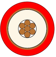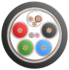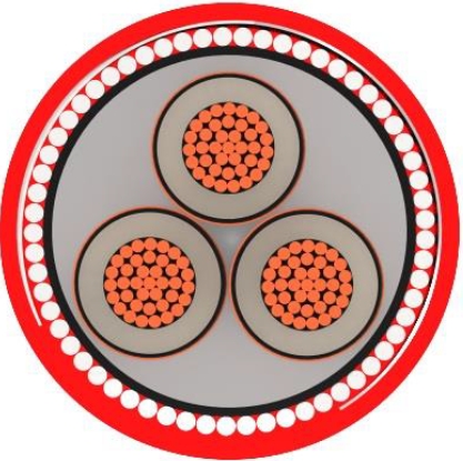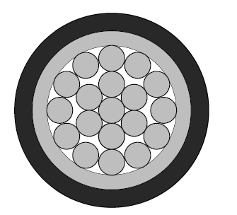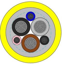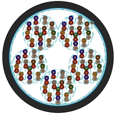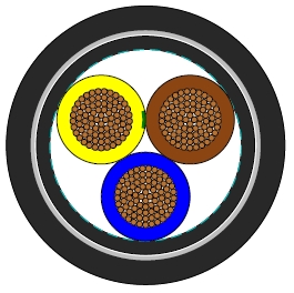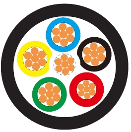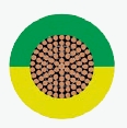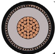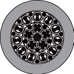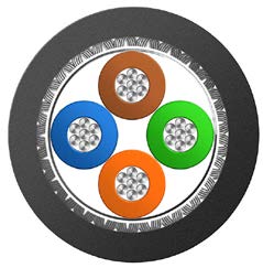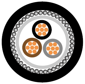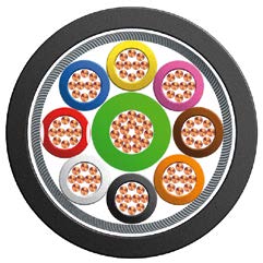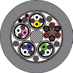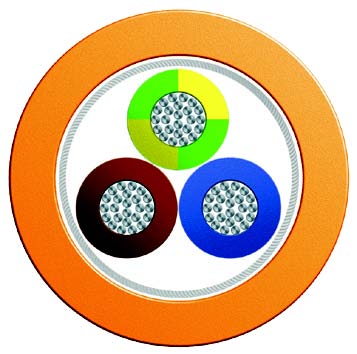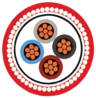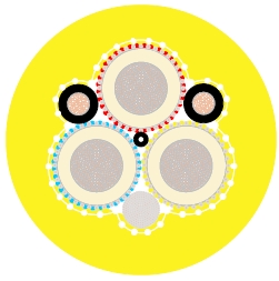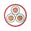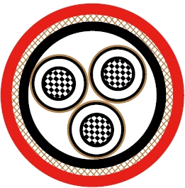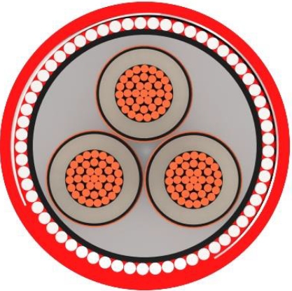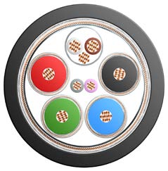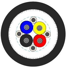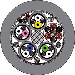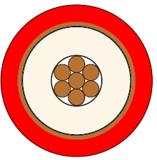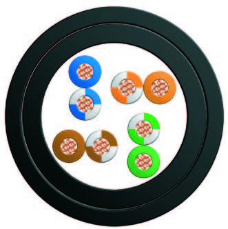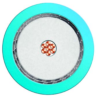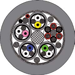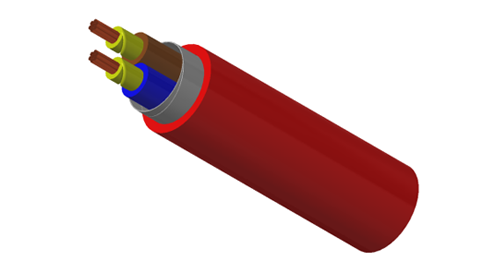
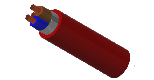
BURY CABLE FirePro FRP300-SOZ1-U/R is a 300/500V screened cable with fire resistant silicone rubber insulation and an LSZH sheath. It is intended for fixed wiring in fire detection, fire alarm and emergency lighting circuits.
Typical projects include commercial buildings, offices, hotels, hospitals and public facilities. Voice alarm, emergency voice communication and auxiliary control circuits may also be considered where the system specification accepts this cable construction.
Select the core count, conductor size and circuit integrity requirements for the actual circuit. Confirm compatibility with the connected equipment, cable supports and terminations. Project acceptance depends on the specified cable and supporting test documentation.
300/500V rating with copper conductors in class 1 or class 2, as specified.
Fire resistant EI 2 silicone rubber insulation and LTS 3 LSZH outer sheath.
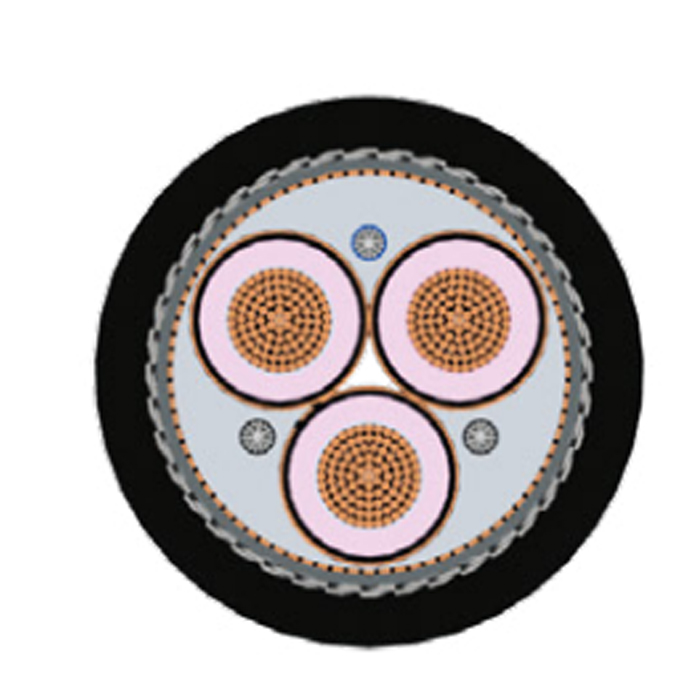
Metallic or laminated metallic tape screen in contact with the CPC or drain wire.
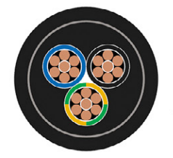
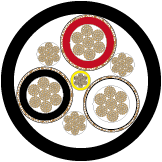
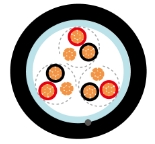
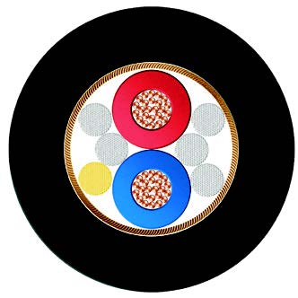
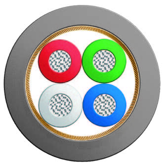
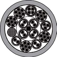
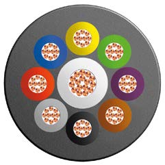
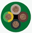
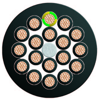
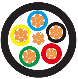
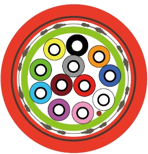
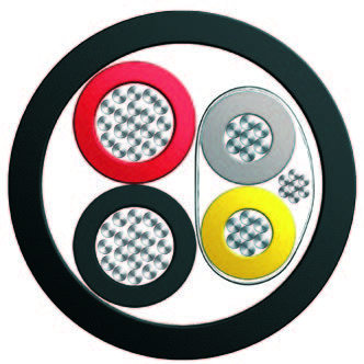
2, 3 and 4 core constructions with a full-size circuit protective conductor; 7, 12 and 19 core options with a drain wire.
Construction dimensions, weights, current ratings and voltage-drop data are provided below for selection checks.
Basic design to BS 7629-1:2015
| Circuit Integrity | BS 6387; BS EN50200 |
| Flame Retardance (single vertical wire or cable test) | IEC 60332-1-2; EN 60332-1-2 |
| Reduced fire Propagation (Vertically-mounted bundled wires & cables test) | IEC 60332-3-24; EN 60332-3-24 |
| Halogen free | IEC 60754-1; EN 50267-2-1 |
| No corrosive Gas emission | IEC 60754-2; EN 50267-2-2 |
| Minimum smoke emission | IEC 61034-2; EN 61034-2 |
300/500V
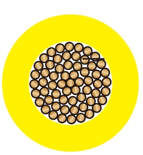
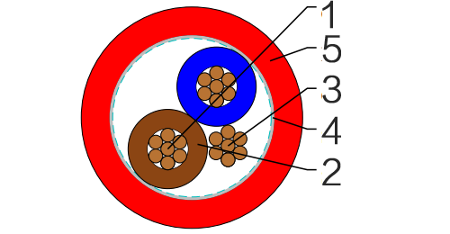
Conductor : Copper conductor according to BS EN 60228 class 1/2.
Insulation : Fire resistant special ceramized silicone rubber compound type EI 2 as per BS EN 50363-1.
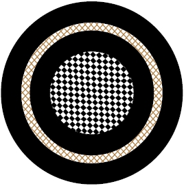
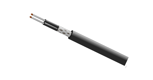
Screened : One or more metallic or laminated metallic tape(s) shall be applied, either longitudinally or helically or a combination of both, with the metallic element in contact with the uninsulated circuit protective conductor or drain wire.
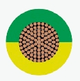
Circuit Protective Conductor : Uninsulated tinned copper conductor of the same section and class as the insulated conductors in the two,three and four cores cables.
Sheath : Extruded LSZH type LTS 3 according to BS 7655-6.1.
Insulation Option : UV resistance, hydrocarbon resistance, oil resistance, anti-rodent and anti-termite properties can be offered as option.
Insulation Colour :
| Number of cores | Core colours or numbering |
| 2 cores+uninsulated circuit protective conductor | Brown, Blue or Brown, Brown |
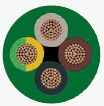
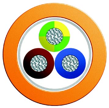
| 3 cores+uninsulated circuit protective conductor | Brown, Black, Grey |
| 4 cores+uninsulated circuit protective conductor | Brown, Blue, Black, Grey |
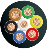
| 7, 12 and19 cores+uninsulated drain wire | Numbers 1, 2, 3, 4, 5, 6, 7 and upwards or, for identification by colour, an identical colour(excluding brown and black),except for two adjacent cores in each layer distinctively coloured brown and black. |
Sheath Colour : Colours upon request.
Maximum temperature range during operation : 60°C
Maximum short circuit temperature (5 Seconds) : 250°C
Minimum bending radius : 6 x Overall Diameter
| Conductor | FRP300-SOZ1-U/R PH30/PH60 | |||||
|---|---|---|---|---|---|---|
| No. of Cores × Cross-sectional Area | Conductor Class | Nominal Insulation Thickness | CPC Nominal Cross-sectional Area | Nominal Sheath Thickness | Approx. Overall Diameter | Approx. Weight |
| no.×mm² | mm | mm² | mm | mm | kg/km | |
| 2 cores | ||||||
| 2x1.0 | 1/2 | 0.6 | 1.0 | 0.9 | 8.0 | 78 |
| 2x1.5 | 1/2 | 0.7 | 1.5 | 0.9 | 8.5 | 103 |
| 2x2.5 | 1/2 | 0.8 | 2.5 | 1.0 | 10.5 | 150 |
| 2x4.0 | 1/2 | 0.8 | 4.0 | 1.1 | 12.5 | 212 |
| 3 cores | ||||||
| 3x1.5 | 1/2 | 0.7 | 1.5 | 0.9 | 9.5 | 130 |
| 3x2.5 | 1/2 | 0.8 | 2.5 | 1.0 | 11.5 | 191 |
| 3x4.0 | 1/2 | 0.8 | 4.0 | 1.1 | 13.5 | 273 |
| 4 cores | ||||||
| 4x1.5 | 1/2 | 0.7 | 1.5 | 1.0 | 10.5 | 165 |
| 4x2.5 | 1/2 | 0.8 | 2.5 | 1.1 | 12.0 | 242 |
| 4x4.0 | 1/2 | 0.8 | 4.0 | 1.2 | 15.0 | 344 |
| 7 cores | ||||||
| 7x1.5 | 1/2 | 0.7 | 0.5 | 1.1 | 12.5 | 257 |
| 7x2.5 | 1/2 | 0.8 | 0.5 | 1.2 | 15.0 | 568 |
| 12 cores | ||||||
| 12x1.5 | 1/2 | 0.7 | 0.5 | 1.2 | 16.0 | 414 |
| 12x2.5 | 1/2 | 0.8 | 0.5 | 1.4 | 20.0 | 886 |
| 19 cores | ||||||
| 19x1.5 | 1/2 | 0.7 | 0.5 | 1.3 | 19.0 | 617 |
Conductor operating temperature : 70°C
Ambient temperature : 30°C
| Conductor cross-sectional area | Ref. Method A (enclosed in conduit in thermally insulating wall etc) | Ref. Method B (enclosed in conduit on a wall or in trunking etc) | Ref. Method C (clipped direct) | Ref. Method E (in free air or on a perforated cable tray etc. horizontal or vertical) | ||||
|---|---|---|---|---|---|---|---|---|
| 1 two-core cable*, single-phase a.c. or d.c. | 1 three-core or 1 four-core cable*, three-phase a.c. | 1 two-core cable*, singlephase a.c. or d.c. | 1 three-core or 1 four-core cable*, three-phase a.c. | 1 two-core cable*, single-phase a.c. or d.c. | 1 three-core or 1 four-core cable*, three-phase a.c. | 1 two-core cable*, single-phase a.c. or d.c. | 1 three-core or 1 four-core cable*, three-phase a.c. | |
| 1 | 2 | 3 | 4 | 5 | 6 | 7 | 8 | 9 |
| mm² | A | A | A | A | A | A | A | A |
| 1.0 | 11 | 10 | 13 | 11.5 | 15 | 13.5 | 17 | 14.5 |
| 1.5 | 14 | 13 | 16.5 | 15 | 19.5 | 17.5 | 22 | 18.5 |
| 2.5 | 18.5 | 17.5 | 23 | 20 | 27 | 24 | 30 | 25 |
| 4 | 25 | 23 | 30 | 27 | 36 | 32 | 40 | 34 |
Note: *With or without a protective conductor.
| Conductor cross-sectional area | Two-core cable d.c. | Two-core cable single-phase a.c. | Three- or four-core cable, three-phase a.c. |
|---|---|---|---|
| 1 | 2 | 3 | 4 |
| mm² | mV/A/m | mV/A/m | mV/A/m |
| 1.0 | 44 | 44 | 38 |
| 1.5 | 29 | 29 | 25 |
| 2.5 | 18 | 18 | 15 |
| 4 | 11 | 11 | 9.5 |
Specify voltage, core count, conductor cross-section, quantity, route length and connected load. Check current capacity and voltage drop for the installation method.
Confirm the required fire test standard, circuit integrity duration and matching test report for the supplied construction. A standard reference alone does not confirm a particular fire classification.
Check the CPC or drain-wire arrangement for the selected core count. Plan screen continuity and earthing to suit the system design.
The metallic screen is not mechanical armour. Confirm protection for exposed routes; outdoor, buried or continuously wet installations require a separate suitability review.
Confirm UV, oil, hydrocarbon, rodent or termite resistance when required. These are optional requirements, not automatic properties of every supply.
The thermal section states 60°C, while the current-rating table uses a 70°C conductor and 30°C ambient basis. Confirm the permissible service temperature before using those ratings, and apply the relevant installation, grouping and ambient corrections.
Other BS 7629-1 screened fire resistant constructions: compare the insulation system, core layout and documented fire performance before substitution.
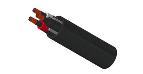
Armoured fire resistant power cables: consider where the circuit voltage or mechanical protection requirements call for a different construction.
Fire resistant instrumentation cables: consider for paired signal circuits where individual or overall screening is specified.
What insulation does this cable use?
This version uses fire resistant silicone rubber insulation, with a metallic screen and an LSZH sheath.
Which core counts are listed?
The specification table lists 2, 3, 4, 7, 12 and 19 core constructions. Available cross-sections differ by core count; refer to the corresponding table row.
Does the screen provide armour protection?
No. The metallic screen and the CPC or drain wire form part of the screened construction. Assess mechanical protection separately for the cable route.
How do I confirm the required fire performance?
State the project test standard and circuit integrity duration. Ask for documentation covering the proposed construction and size before confirming the order.
What should I include in an enquiry?
Send the core count, cross-section, quantity, application, installation conditions, sheath colour, delivery destination and required test documents.