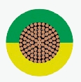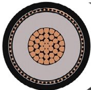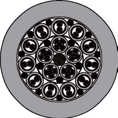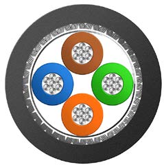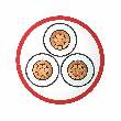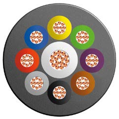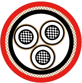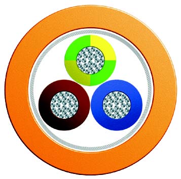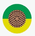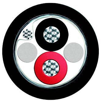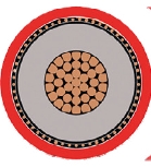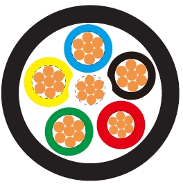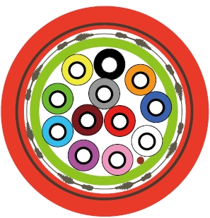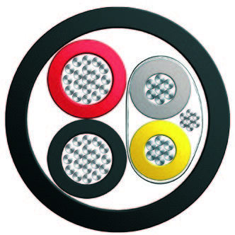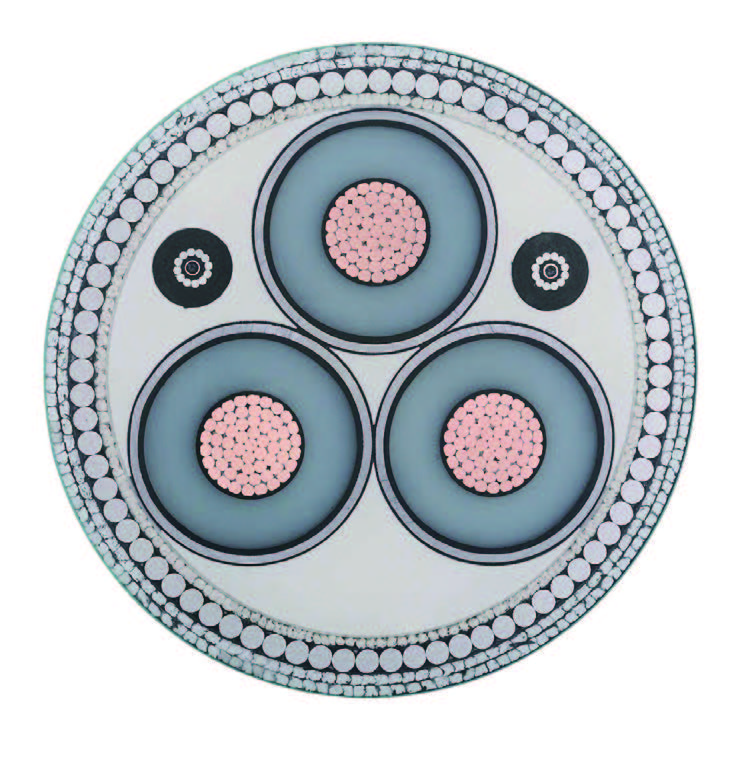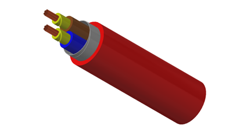
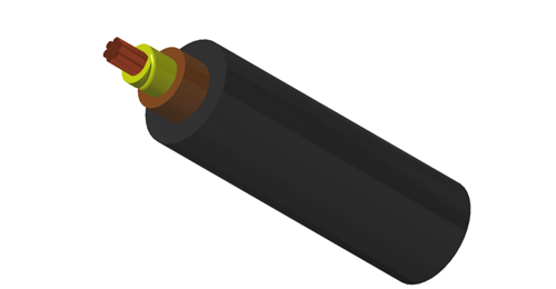
BURY CABLE supplies this 600/1000V single core mica XLPE LSZH cable for essential power circuits in buildings, transport facilities and industrial installations. The mica glass tape forms the fire barrier, while the LSZH sheath supports low-smoke and halogen-free requirements. Use protected trays, ducts, conduits and trunking as part of the specified cable installation system.
Basic design adapted from IEC 60502-1
| Circuit Integrity | IEC 60331-21; EN 6387; BS 8491 |
| Flame Retardance (Single vertical wire or cable test) | IEC 60332-1-2; EN 60332-1-2 |
| Reduced fire Propagation (Vertically-mounted bundled wires & cables test) | IEC 60332-3-24; EN 60332-3-24 |
| Halogen Free | IEC 60754-1; EN 50267-2-1 |
| No Corrosive Gas Emission | IEC 60754-2; EN 50267-2-2 |
| Minimum Smoke Emission | IEC 61034-2; EN 61034-2 |
600/1000V
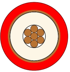
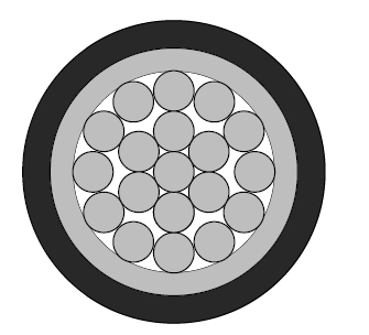
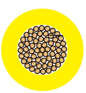
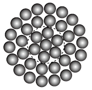
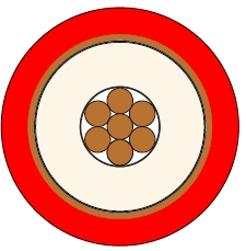
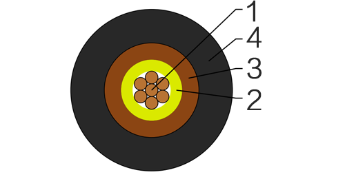
Conductor : The conductors shall be class 2 plain or metal-coated annealed copper in accordance with IEC 60228. Class 1 and class 5 conductor can be offered as option.
Fire Barrier : Mica glass tape.
Insulation : Thermosetting XLPE compound as per IEC 60502-1.
Outer Sheath : Thermoplastic halogen free compound ST8 as per IEC 60502-1.
Outer Sheath Option : UV resistance, hydrocarbon resistance, oil resistance, anti-rodent and anti-termite properties can be offered as option.
Insulation Colour : Brown or blue; other colours can be offered upon request.
Sheath Colour : Black; other colours can be offered upon request.
Maximum temperature range during operation : 90°C
Maximum short circuit temperature (5 Seconds) : 250°C
Minimum bending radius
circular copper conductors OD≤25mm : 4 × Overall Diameter
circular copper conductors OD﹥25mm : 6 × Overall Diameter
shaped copper conductors : 8 × Overall Diameter
| Conductor | FRP600-mRZ1-R | ||||
|---|---|---|---|---|---|
| No. of Cores × Cross-sectional Area | Conductor Class | Nominal Insulation Thickness | Nominal Sheath Thickness | Approx. Overall Diameter | Approx. Weight |
| No.×mm² | mm | mm | mm | kg/km | |
| 1×1.5 | 2 | 0.7 | 1.4 | 6.8 | 58 |
| 1×2.5 | 2 | 0.7 | 1.4 | 7.2 | 71 |
| 1×4 | 2 | 0.7 | 1.4 | 7.8 | 92 |
| 1×6 | 2 | 0.7 | 1.4 | 8.3 | 118 |
| 1×10 | 2 | 0.7 | 1.4 | 9.3 | 168 |
| 1×16 | 2 | 0.7 | 1.4 | 10.3 | 238 |
| 1×25 | 2 | 0.9 | 1.4 | 12.0 | 352 |
| 1×35 | 2 | 0.9 | 1.4 | 13.2 | 463 |
| 1×50 | 2 | 1.0 | 1.4 | 14.7 | 606 |
| 1×70 | 2 | 1.1 | 1.4 | 16.7 | 843 |
| 1×95 | 2 | 1.1 | 1.5 | 18.8 | 1139 |
| 1×120 | 2 | 1.2 | 1.5 | 20.6 | 1416 |
| 1×150 | 2 | 1.4 | 1.6 | 22.8 | 1736 |
| 1×185 | 2 | 1.6 | 1.6 | 25.0 | 2154 |
| 1×240 | 2 | 1.7 | 1.7 | 28.1 | 2798 |
| 1×300 | 2 | 1.8 | 1.8 | 30.9 | 3479 |
| 1×400 | 2 | 2.0 | 1.9 | 34.5 | 4419 |
| 1×500 | 2 | 2.2 | 2.0 | 38.2 | 5535 |
| 1×630 | 2 | 2.4 | 2.2 | 43.0 | 7113 |
| 1×800 | 2 | 2.6 | 2.3 | 47.9 | 9026 |
| 1×1000 | 2 | 2.8 | 2.4 | 53.0 | 11302 |
Conductor operating temperature : 90°C
Ambient temperature : 30°C
| Conductor cross-sectional area | Ref. Method A (enclosed in conduit in thermally insulating wall etc.) | Ref. Method B (enclosed in conduit on a wall or in trunking etc.) | Ref. Method C (clipped direct) | Ref. Method F (in free air or on a perforated cable tray, horizontal or vertical etc.) Touching | Ref. Method G (in free air) Spaced by one cable diameter | ||||||
|---|---|---|---|---|---|---|---|---|---|---|---|
| 2 cables, single-phase a.c. or d.c. | 3 or 4 cables, three-phase a.c. | 2 cables, single-phase a.c. or d.c | 3 or 4 cables, three-phase a.c. | 2 cables, single-phase a.c. or d.c. flat and touching | 3 or 4 cables, three-phase a.c. flat and touching or trefoil | 2 cables, single-phase a.c. or d.c. flat | 3 cables, three-phasea.c. flat | 3 cables, three-phase a.c. trefoil | 2 cables, single-phasea.c. or d.c. or 3 cablesthree-phase a.c. flat | ||
| Horizontal | Vertical | ||||||||||
| 1 | 2 | 3 | 4 | 5 | 6 | 7 | 8 | 9 | 10 | 11 | 12 |
| mm² | A | A | A | A | A | A | A | A | A | A | A |
| 1.5 | 19 | 17 | 23 | 20 | 25 | 23 | - | - | - | - | - |
| 2.5 | 26 | 23 | 31 | 28 | 34 | 31 | - | - | - | - | - |
| 4 | 35 | 31 | 42 | 37 | 46 | 41 | - | - | - | - | - |
| 6 | 45 | 40 | 54 | 48 | 59 | 54 | - | - | - | - | - |
| 10 | 61 | 54 | 75 | 66 | 81 | 74 | - | - | - | - | - |
| 16 | 81 | 73 | 100 | 88 | 109 | 99 | - | - | - | - | - |
| 25 | 106 | 95 | 133 | 117 | 143 | 130 | 161 | 141 | 135 | 182 | 161 |
| 35 | 131 | 117 | 164 | 144 | 176 | 161 | 200 | 176 | 169 | 226 | 201 |
| 50 | 158 | 141 | 198 | 175 | 228 | 209 | 242 | 216 | 207 | 275 | 246 |
| 70 | 200 | 179 | 253 | 222 | 293 | 268 | 310 | 279 | 268 | 353 | 318 |
| 95 | 241 | 216 | 306 | 269 | 355 | 326 | 377 | 342 | 328 | 430 | 389 |
| 120 | 278 | 249 | 354 | 312 | 413 | 379 | 437 | 400 | 383 | 500 | 454 |
| 150 | 318 | 285 | 393 | 342 | 476 | 436 | 504 | 464 | 444 | 577 | 527 |
| 185 | 362 | 324 | 449 | 384 | 545 | 500 | 575 | 533 | 510 | 661 | 605 |
| 240 | 424 | 380 | 528 | 450 | 644 | 590 | 679 | 634 | 607 | 781 | 719 |
| 300 | 486 | 435 | 603 | 514 | 743 | 681 | 783 | 736 | 703 | 902 | 833 |
| 400 | - | - | 683 | 584 | 868 | 793 | 940 | 868 | 823 | 1085 | 1008 |
| 500 | - | - | 783 | 666 | 990 | 904 | 1083 | 998 | 946 | 1253 | 1169 |
| 630 | - | - | 900 | 764 | 1130 | 1033 | 1254 | 1151 | 1088 | 1454 | 1362 |
| 800 | - | - | - | - | 1288 | 1179 | 1358 | 1275 | 1214 | 1581 | 1485 |
| 1000 | - | - | - | - | 1443 | 1323 | 1520 | 1436 | 1349 | 1775 | 1671 |
| Conductor cross-sectional area | 2 cables d.c. | 2 cables, single-phase a.c. | 3 or 4 cables, three-phase a.c. | |||||||||||||||||||
|---|---|---|---|---|---|---|---|---|---|---|---|---|---|---|---|---|---|---|---|---|---|---|
| Ref. Methods A&B (enclosed in conduit or trunking) | Ref. Methods C, F&G (clipped direct, on trays or in free air) | Ref. Methods A&B(enclosed in conduit or trunking) | Ref. Methods C, F&G (clipped direct, on trays or in free air) | |||||||||||||||||||
| Cables touching | Cables spaced* | Cables touching, Trefoil | Cables touching, Flat | Cables spaced*, Flat | ||||||||||||||||||
| 1 | 2 | 3 | 4 | 5 | 6 | 7 | 8 | 9 | ||||||||||||||
| mm² | A | A | A | A | A | A | A | A | ||||||||||||||
| 2.5 | 19 | 19 | 19 | 19 | 16 | 16 | 16 | 16 | ||||||||||||||
| 4 | 12 | 12 | 12 | 12 | 10 | 10 | 10 | 10 | ||||||||||||||
| 6 | 7.9 | 7.9 | 7.9 | 7.9 | 6.8 | 6.8 | 6.8 | 6.8 | ||||||||||||||
| 10 | 4.7 | 4.7 | 4.7 | 4.7 | 4.0 | 4.0 | 4.0 | 4.0 | ||||||||||||||
| 16 | 2.9 | 2.9 | 2.9 | 2.9 | 2.5 | 2.5 | 2.5 | 2.5 | ||||||||||||||
| r | x | z | r | x | z | r | x | z | r | x | z | r | x | z | r | x | z | r | x | z | ||
| 25 | 1.85 | 1.85 | 0.31 | 1.90 | 1.85 | 0.190 | 1.85 | 1.85 | 0.28 | 1.85 | 1.60 | 0.27 | 1.65 | 1.60 | 0.165 | 1.60 | 1.60 | 0.190 | 1.60 | 1.60 | 0.27 | 1.65 |
| 35 | 1.35 | 1.35 | 0.29 | 1.35 | 1.35 | 0.180 | 1.35 | 1.35 | 0.27 | 1.35 | 1.15 | 0.25 | 1.15 | 1.15 | 0.155 | 1.15 | 1.15 | 0.180 | 1.15 | 1.15 | 0.26 | 1.20 |
| 50 | 0.99 | 1.00 | 0.29 | 1.05 | 0.99 | 0.180 | 1.00 | 0.99 | 0.27 | 1.00 | 0.87 | 0.25 | 0.90 | 0.86 | 0.155 | 0.87 | 0.86 | 0.180 | 0.87 | 0.86 | 0.26 | 0.89 |
| 70 | 0.68 | 0.70 | 0.28 | 0.75 | 0.68 | 0.175 | 0.71 | 0.68 | 0.26 | 0.73 | 0.60 | 0.24 | 0.65 | 0.59 | 0.150 | 0.61 | 0.59 | 0.175 | 0.62 | 0.59 | 0.25 | 0.65 |
| 95 | 0.49 | 0.51 | 0.27 | 0.58 | 0.49 | 0.170 | 0.52 | 0.49 | 0.26 | 0.56 | 0.44 | 0.23 | 0.50 | 0.43 | 0.145 | 0.45 | 0.43 | 0.170 | 0.46 | 0.43 | 0.25 | 0.49 |
| 120 | 0.39 | 0.41 | 0.26 | 0.48 | 0.39 | 0.165 | 0.43 | 0.39 | 0.25 | 0.47 | 0.35 | 0.23 | 0.42 | 0.34 | 0.140 | 0.37 | 0.34 | 0.165 | 0.38 | 0.34 | 0.24 | 0.42 |
| 150 | 0.32 | 0.33 | 0.26 | 0.43 | 0.32 | 0.165 | 0.36 | 0.32 | 0.25 | 0.41 | 0.29 | 0.23 | 0.37 | 0.28 | 0.140 | 0.31 | 0.28 | 0.165 | 0.32 | 0.28 | 0.24 | 0.37 |
| 185 | 0.25 | 0.27 | 0.26 | 0.37 | 0.26 | 0.165 | 0.30 | 0.25 | 0.25 | 0.36 | 0.23 | 0.23 | 0.32 | 0.22 | 0.140 | 0.26 | 0.22 | 0.165 | 0.28 | 0.22 | 0.24 | 0.33 |
| 240 | 0.190 | 0.21 | 0.26 | 0.33 | 0.20 | 0.160 | 0.25 | 0.195 | 0.25 | 0.31 | 0.185 | 0.22 | 0.29 | 0.170 | 0.140 | 0.22 | 0.170 | 0.165 | 0.24 | 0.170 | 0.24 | 0.29 |
| 300 | 0.155 | 0.175 | 0.25 | 0.31 | 0.160 | 0.160 | 0.22 | 0.155 | 0.25 | 0.29 | 0.150 | 0.22 | 0.27 | 0.140 | 0.140 | 0.195 | 0.135 | 0.160 | 0.21 | 0.135 | 0.24 | 0.27 |
| 400 | 0.120 | 0.140 | 0.25 | 0.29 | 0.130 | 0.155 | 0.20 | 0.125 | 0.24 | 0.27 | 0.125 | 0.22 | 0.25 | 0.110 | 0.135 | 0.175 | 0.110 | 0.160 | 0.195 | 0.110 | 0.24 | 0.26 |
| 500 | 0.093 | 0.120 | 0.25 | 0.28 | 0.105 | 0.155 | 0.185 | 0.098 | 0.24 | 0.26 | 0.100 | 0.22 | 0.24 | 0.090 | 0.135 | 0.160 | 0.088 | 0.160 | 0.180 | 0.085 | 0.24 | 0.25 |
| 630 | 0.072 | 0.100 | 0.25 | 0.27 | 0.086 | 0.155 | 0.175 | 0.078 | 0.24 | 0.25 | 0.088 | 0.21 | 0.23 | 0.074 | 0.135 | 0.150 | 0.071 | 0.160 | 0.170 | 0.068 | 0.23 | 0.24 |
| 800 | 0.056 | - | 0.072 | 0.150 | 0.170 | 0.064 | 0.24 | 0.25 | - | 0.062 | 0.130 | 0.145 | 0.059 | 0.155 | 0.165 | 0.055 | 0.23 | 0.24 | ||||
| 1000 | 0.045 | - | 0.063 | 0.150 | 0.165 | 0.054 | 0.24 | 0.24 | - | 0.055 | 0.130 | 0.145 | 0.050 | 0.155 | 0.165 | 0.047 | 0.23 | 0.24 | ||||
Note : *Spacings larger than one cable diameter will result in a large voltage drop.
r = conductor resistance at operating temperature
x = reactance
z = impedance
Class 2 plain or metal-coated annealed copper, with Class 1 and Class 5 offered as options; mica glass tape and thermosetting XLPE insulation.
Unarmoured construction with a thermoplastic halogen-free ST8 outer sheath.
Construction schedule: 1.5-1000 mm² single-core Class 2 copper.
Specify the required circuit-integrity test method, classification and duration together with compatible supports and terminations. Match the selected cable and installation system to the project fire strategy.
Apply the published current-rating and voltage-drop references to the matching circuit arrangement, installation method and temperatures, including the applicable correction factors.
Circular conductors use 4 times overall diameter up to 25 mm cable diameter and 6 times above 25 mm; shaped conductors use 8 times overall diameter. State any UV, oil, hydrocarbon, rodent or termite sheath options in the order.
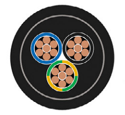
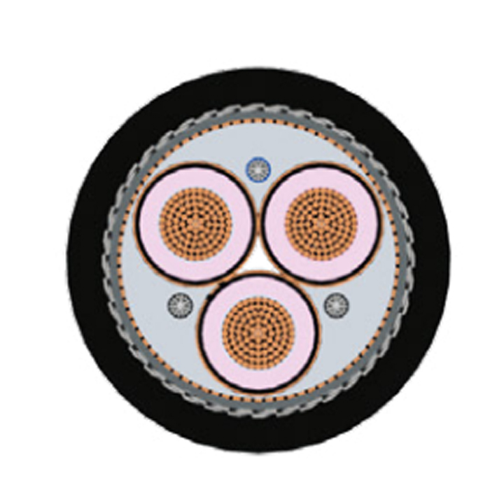
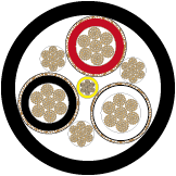
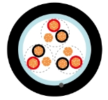
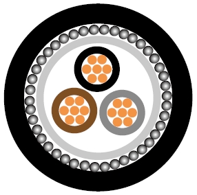
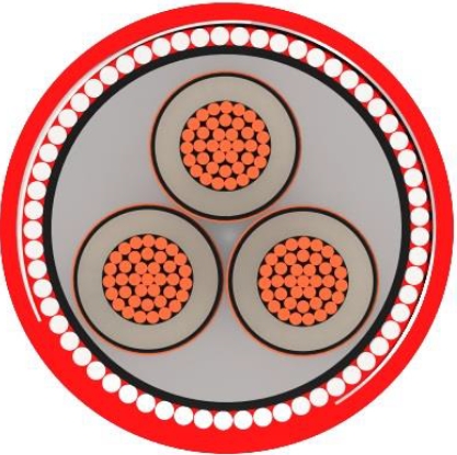
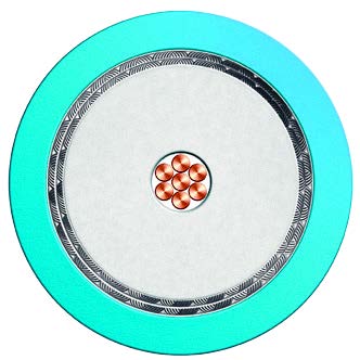
600/1000V Single Core Mica XLPE AWA LSZH Fire Resistant Cable to IEC 60502-1
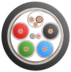
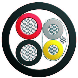
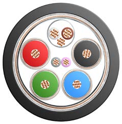
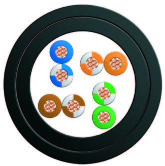
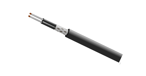
600/1000V Multicore Mica XLPE LSZH Fire Resistant Cable to IEC 60502-1
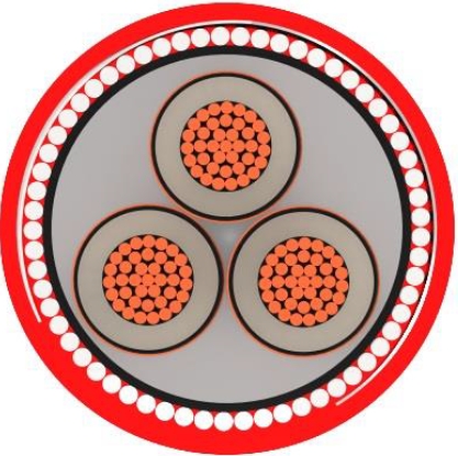
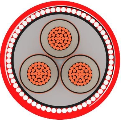
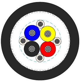
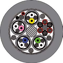
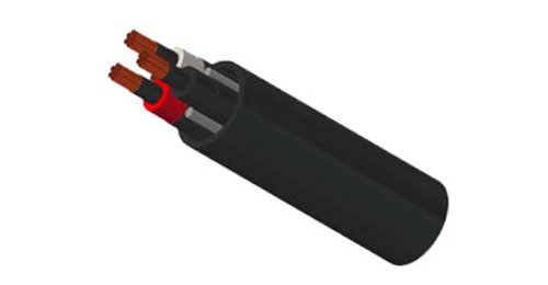
600/1000V Multicore Mica XLPE SWA LSZH Fire Resistant Cable to IEC 60502-1
It forms the fire barrier around the conductor and supports the cable design for circuit integrity during fire testing.
Low Smoke Zero Halogen. The sheath is a thermoplastic halogen-free ST8 compound, with smoke and gas test references listed in the fire-performance table.
The construction schedule covers 1.5-1000 mm². Select the exact row for conductor size, diameter and weight.
Unarmoured construction with a thermoplastic halogen-free ST8 outer sheath. The installation provides additional mechanical protection where required.
The stated maximum operating temperature is 90°C and the maximum short-circuit temperature is 250°C for 5 seconds.