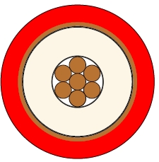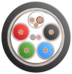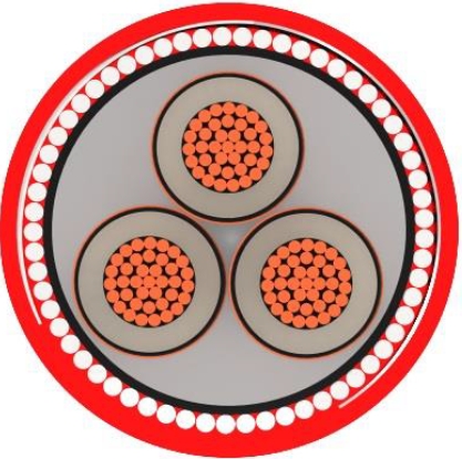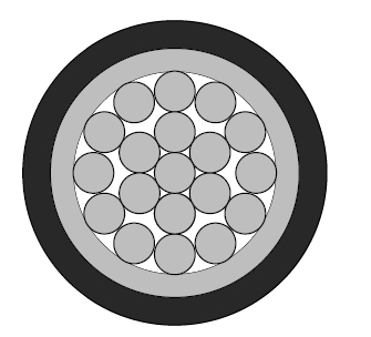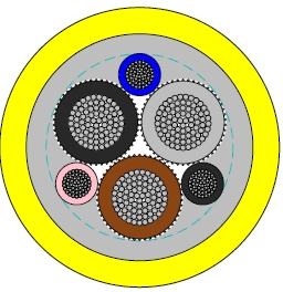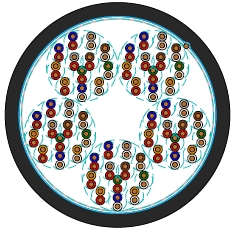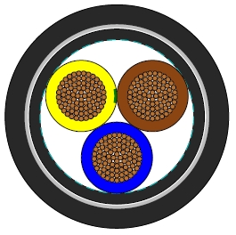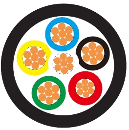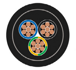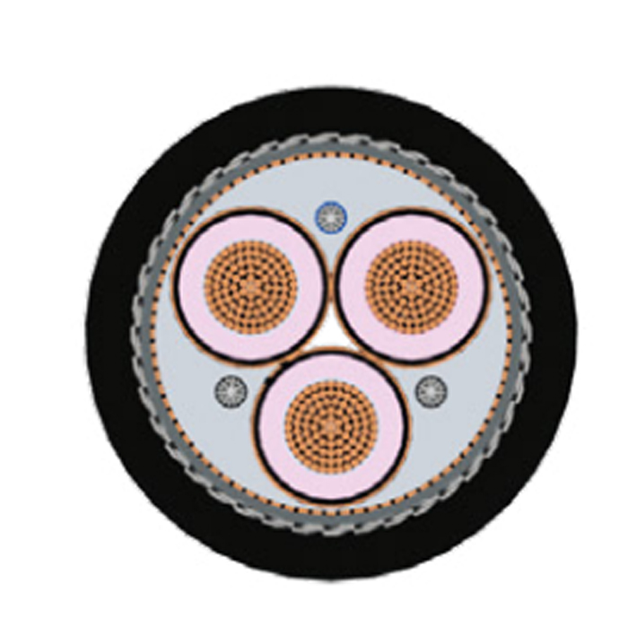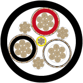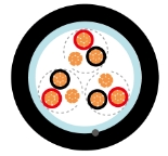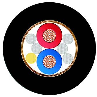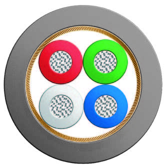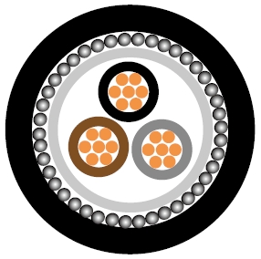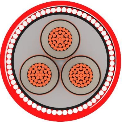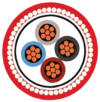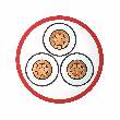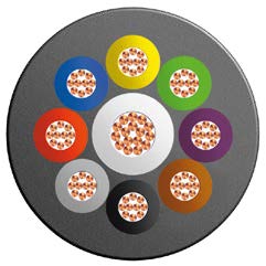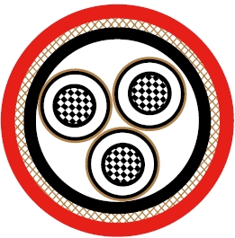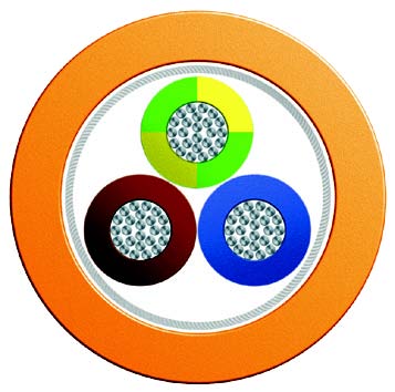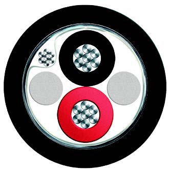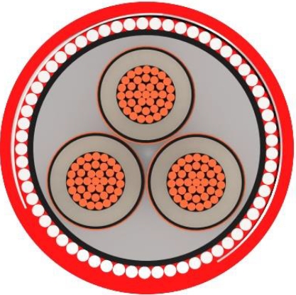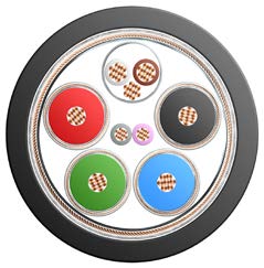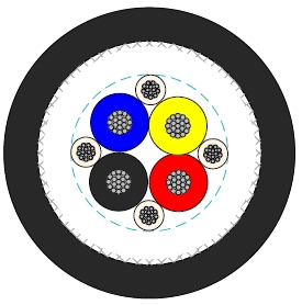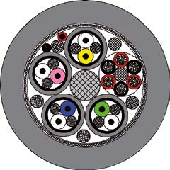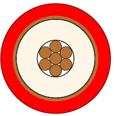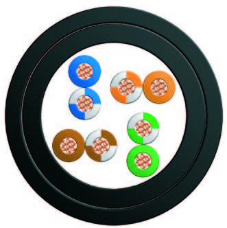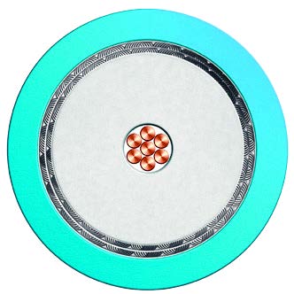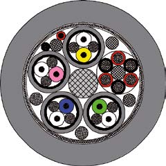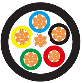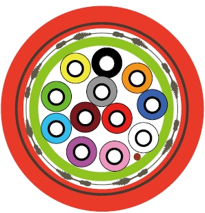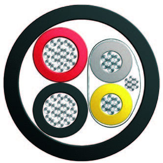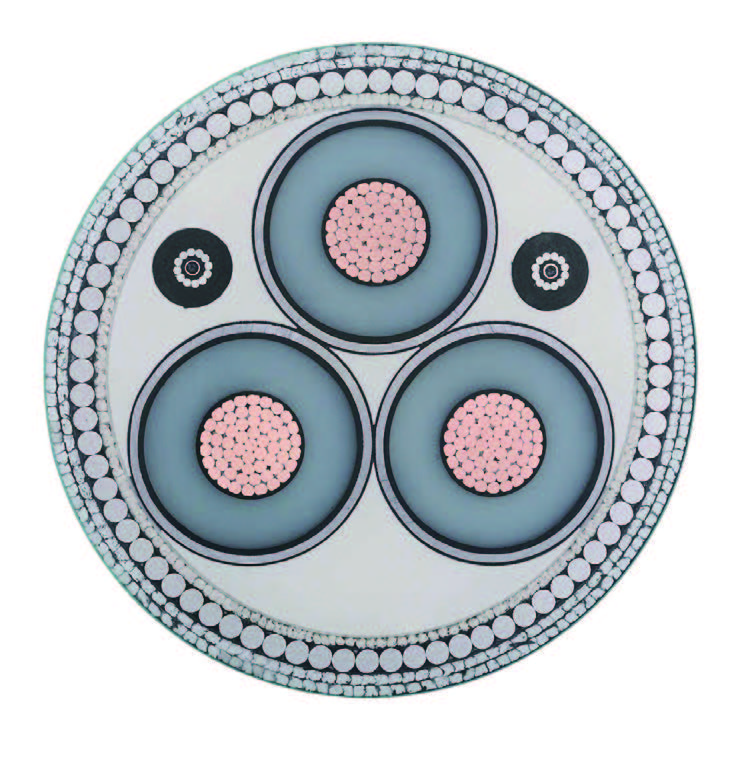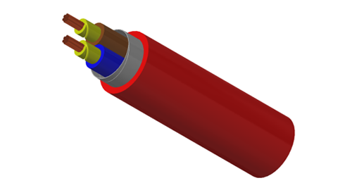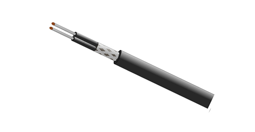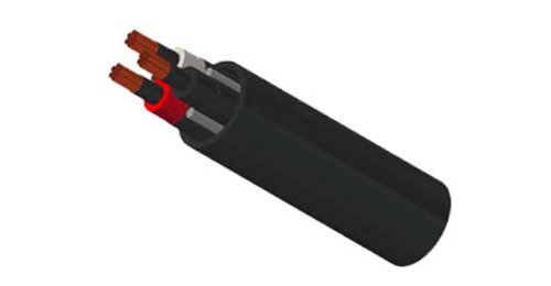
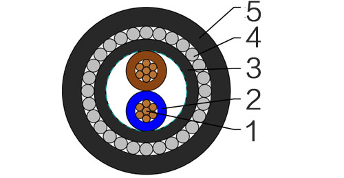
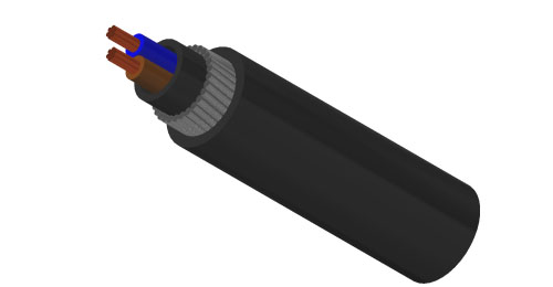
BURY CABLE BS 5467 600/1000V multicore copper cable is designed for fixed low voltage power distribution in buildings, industrial plants and infrastructure projects. The construction uses Class 2 stranded copper, XLPE insulation, PVC bedding, galvanized steel wire armour (SWA) and a PVC outer sheath.
The construction table covers 2, 3 and 4 cores from 1.5 to 400 mm², and 5 cores from 1.5 to 70 mm². Typical routes include cable trays, ducts and trenches. Underground or direct burial use depends on the project design, site conditions and installation requirements.
Select the core count, conductor area and installation method together. Dimensions and weights are separate from electrical ratings; use the notes below when reading the current and voltage-drop tables.
Basic design to BS 5467
| Flame Retardance (Single Vertical Wire Test) | BS EN 60332-1-2 |
600/1000V
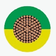
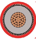
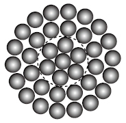
| Conductor | Annealed copper wire, stranded according to BS EN 60228 class 2. |
| Insulation | Extruded XLPE GP 8 according to BS 7655-1.3. |
| Bedding | PVC. |
| Armouring | Galvanized steel wire |
| Outer Sheath | PVC Type 9 according to BS 7655-4.2. |
| Outer Sheath Option | UV resistance, hydrocarbon resistance, oil resistance, anti rodent and anti termite properties can be offered as option. Compliance to fire performance standard (IEC 60332-1, IEC 60332-3,UL 1581, UL 1666 etc) depends on the oxygen index of the PVC compound and the overall cable design. LSPVC can also be provided upon request. |
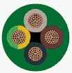
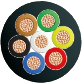
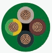
| Insulation Colour | Two-core: Brown, blue Three-core: Brown, black, grey Four-core: Blue, brown, black, grey Five-core: Green-and-yellow, blue, brown, black, grey |
| Sheath Colour | Black, other colours can be offered upon request. |
| Maximum temperature range during operation (XLPE) | 90°C |
| Maximum short circuit temperature (5 Seconds) | 250°C |
| Minimum bending radius | 8 x Overall Diameter |
| Conductor | FLP600-RVMV-R | ||||||
|---|---|---|---|---|---|---|---|
| No. of Cores x Cross Section | Class of Conductor | Nominal Insulation Thickness | Nominal Bedding Thickness | Nominal Armour Wire Diameter | Nominal Sheath Thickness | Approx. Overall Diameter | Approx. Weight |
| No.xmm² | mm | mm | mm | mm | mm | kg/km | |
| 2 Cores | |||||||
| 2x1.5a | 2 | 0.6 | 0.8 | 0.9 | 1.3 | 12.1 | 320 |
| 2x2.5a | 2 | 0.7 | 0.8 | 0.9 | 1.4 | 13.6 | 365 |
| 2x4.0a | 2 | 0.7 | 0.8 | 0.9 | 1.4 | 14.7 | 440 |
| 2x6.0a | 2 | 0.7 | 0.8 | 0.9 | 1.4 | 15.9 | 470 |
| 2x10a | 2 | 0.7 | 0.8 | 0.9 | 1.5 | 18.0 | 800 |
| 2x16a | 2 | 0.7 | 0.8 | 1.25 | 1.5 | 20.4 | 900 |
| 2x25b | 2 | 0.9 | 0.8 | 1.25 | 1.6 | 20.4 | 1240 |
| 2x25a | 2 | 0.9 | 0.8 | 1.25 | 1.6 | 24.1 | 1240 |
| 2x35b | 2 | 0.9 | 1.0 | 1.6 | 1.7 | 23.3 | 1710 |
| 2x35a | 2 | 0.9 | 1.0 | 1.6 | 1.7 | 27.7 | 1710 |
| 2x50b | 2 | 1.0 | 1.0 | 1.6 | 1.8 | 25.8 | 1800 |
| 2x70b | 2 | 1.1 | 1.0 | 1.6 | 1.9 | 29.0 | 2320 |
| 2x95b | 2 | 1.1 | 1.2 | 2.0 | 2.0 | 33.1 | 3150 |
| 2x120b | 2 | 1.2 | 1.2 | 2.0 | 2.1 | 36.1 | 3880 |
| 2x150b | 2 | 1.4 | 1.2 | 2.0 | 2.2 | 39.3 | 4820 |
| 2x185b | 2 | 1.6 | 1.4 | 2.5 | 2.4 | 44.7 | 5920 |
| 2x240b | 2 | 1.7 | 1.4 | 2.5 | 2.5 | 49.0 | 7300 |
| 2x300b | 2 | 1.8 | 1.6 | 2.5 | 2.6 | 53.5 | 8770 |
| 2x400b | 2 | 2.0 | 1.6 | 2.5 | 2.8 | 59.0 | 10905 |
| 3 Cores | |||||||
| 3x1.5a | 2 | 0.6 | 0.8 | 0.9 | 1.3 | 12.6 | 340 |
| 3x2.5a | 2 | 0.7 | 0.8 | 0.9 | 1.4 | 14.1 | 408 |
| 3x4.0a | 2 | 0.7 | 0.8 | 0.9 | 1.4 | 15.3 | 498 |
| 3x6.0a | 2 | 0.7 | 0.8 | 0.9 | 1.4 | 16.6 | 600 |
| 3x10a | 2 | 0.7 | 0.8 | 1.25 | 1.5 | 19.5 | 915 |
| 3x16a | 2 | 0.7 | 0.8 | 1.25 | 1.6 | 21.6 | 1130 |
| 3x25a | 2 | 0.9 | 1.0 | 1.6 | 1.7 | 26.7 | 1710 |
| 3x25b | 2 | 0.9 | 1.0 | 1.6 | 1.7 | 23.6 | 1710 |
| 3x35a | 2 | 0.9 | 1.0 | 1.6 | 1.8 | 29.4 | 2100 |
| 3x35b | 2 | 0.9 | 1.0 | 1.6 | 1.8 | 25.7 | 2100 |
| 3x50b | 2 | 1.0 | 1.0 | 1.6 | 1.8 | 28.5 | 2450 |
| 3x70b | 2 | 1.1 | 1.0 | 1.6 | 1.9 | 32.2 | 3120 |
| 3x95b | 2 | 1.1 | 1.2 | 2.0 | 2.1 | 37.0 | 4310 |
| 3x120b | 2 | 1.2 | 1.2 | 2.0 | 2.2 | 40.4 | 5160 |
| 3x150b | 2 | 1.4 | 1.4 | 2.5 | 2.3 | 45.5 | 7160 |
| 3x185b | 2 | 1.6 | 1.4 | 2.5 | 2.4 | 49.8 | 8600 |
| 3x240b | 2 | 1.7 | 1.4 | 2.5 | 2.6 | 55.1 | 10755 |
| 3x300b | 2 | 1.8 | 1.6 | 2.5 | 2.7 | 60.2 | 13080 |
| 3x400b | 2 | 2.0 | 1.6 | 2.5 | 2.9 | 66.6 | 15810 |
| 4 Cores | |||||||
| 4x1.5a | 2 | 0.6 | 0.8 | 0.9 | 1.3 | 13.3 | 390 |
| 4x2.5a | 2 | 0.7 | 0.8 | 0.9 | 1.4 | 15.0 | 470 |
| 4x4.0a | 2 | 0.7 | 0.8 | 0.9 | 1.4 | 16.4 | 580 |
| 4x6.0a | 2 | 0.7 | 0.8 | 1.25 | 1.5 | 18.7 | 805 |
| 4x10a | 2 | 0.7 | 0.8 | 1.25 | 1.5 | 21.1 | 1090 |
| 4x16a | 2 | 0.7 | 0.8 | 1.25 | 1.6 | 23.4 | 1320 |
| 4x25a | 2 | 0.9 | 1.0 | 1.6 | 1.7 | 28.9 | 1840 |
| 4x25b | 2 | 0.9 | 1.0 | 1.6 | 1.7 | 26.1 | 1840 |
| 4x35a | 2 | 0.9 | 10 | 1.6 | 1.8 | 31.9 | 2310 |
| 4x35b | 2 | 0.9 | 1.0 | 1.6 | 1.8 | 28.6 | 2310 |
| 4x50b | 2 | 1.0 | 1.0 | 1.6 | 1.9 | 32.0 | 2970 |
| 4x70b | 2 | 1.1 | 1.2 | 2.0 | 2.1 | 37.7 | 4240 |
| 4x95b | 2 | 1.1 | 1.2 | 2.0 | 2.2 | 41.7 | 5400 |
| 4x120b | 2 | 1.2 | 1.4 | 2.5 | 2.3 | 47.1 | 7000 |
| 4x150b | 2 | 1.4 | 1.4 | 2.5 | 2.4 | 51.4 | 8350 |
| 4x185b | 2 | 1.6 | 1.4 | 2.5 | 2.6 | 56.6 | 10130 |
| 4x240b | 2 | 1.7 | 1.6 | 2.5 | 2.7 | 63.0 | 12840 |
| 4x300b | 2 | 1.8 | 1.6 | 2.5 | 2.9 | 68.8 | 15530 |
| 4x400b | 2 | 2.0 | 1.8 | 3.15 | 3.2 | 78.1 | 19950 |
| 5 Cores | |||||||
| 5x1.5a | 2 | 0.6 | 0.8 | 0.9 | 1.4 | 14.3 | 430 |
| 5x2.5a | 2 | 0.7 | 0.8 | 0.9 | 1.4 | 16.1 | 545 |
| 5x4.0a | 2 | 0.7 | 0.8 | 0.9 | 1.5 | 17.8 | 680 |
| 5x6.0a | 2 | 0.7 | 0.8 | 1.25 | 1.5 | 20 | 840 |
| 5x10a | 2 | 0.7 | 0.8 | 1.25 | 1.6 | 22.9 | 1105 |
| 5x16a | 2 | 0.7 | 1.0 | 1.6 | 1.7 | 26.6 | 1450 |
| 5x25a | 2 | 0.9 | 1.0 | 1.6 | 1.8 | 31.5 | 2245 |
| 5x35a | 2 | 0.9 | 1.0 | 1.6 | 1.9 | 34.8 | 2840 |
| 5x50a | 2 | 1.0 | 1.2 | 2.0 | 2.0 | 40.4 | 3895 |
| 5x70a | 2 | 1.1 | 1.2 | 2.0 | 2.2 | 46.3 | 5145 |
a Circular or compacted circular stranded conductors (class 2).
b Shaped stranded conductor (class 2).
| Conductor Operating Temperature | 90°C |
| Ambient Temperature | 30°C |
| Conductor crosssectional area | Reference Method C (clipped direct) | Reference Method E (in free air or on a perforated cable tray, horizontal or vertical) | Reference Method D (direct in in groud or in ducting in groud. in or around buildings) | |||
|---|---|---|---|---|---|---|
| 1 two-core cable*, single-phase a.c. or d.c. | 1 three-or four core cable*, three-phase a.c. | 1 two-core cable*, singlephase a.c. or d.c. | 1 three-or four core cable*, three-phase a.c. | 1 two-core cable*, single-phase a.c. or d.c. | 1 three-or four core cable*, threephase a.c. | |
| 1 | 2 | 3 | 4 | 5 | 6 | 7 |
| mm2 | A | A | A | A | A | A |
| 1.5 | 27 | 23 | 29 | 25 | 25 | 21 |
| 2.5 | 36 | 31 | 39 | 33 | 33 | 28 |
| 4.0 | 49 | 42 | 52 | 44 | 43 | 36 |
| 6.0 | 62 | 53 | 66 | 56 | 53 | 44 |
| 10 | 85 | 73 | 90 | 78 | 71 | 58 |
| 16 | 110 | 94 | 115 | 99 | 91 | 75 |
| 25 | 146 | 124 | 152 | 131 | 116 | 96 |
| 35 | 180 | 154 | 188 | 162 | 139 | 115 |
| 50 | 219 | 187 | 228 | 197 | 164 | 135 |
| 70 | 279 | 238 | 291 | 251 | 203 | 167 |
| 95 | 338 | 289 | 354 | 304 | 239 | 197 |
| 120 | 392 | 335 | 410 | 353 | 271 | 223 |
| 150 | 451 | 386 | 472 | 406 | 306 | 251 |
| 185 | 515 | 441 | 539 | 463 | 343 | 281 |
| 240 | 607 | 520 | 636 | 546 | 395 | 324 |
| 300 | 698 | 599 | 732 | 628 | 446 | 365 |
| 400 | 787 | 673 | 847 | 728 | - | - |
| Conductor cross- sectional area | Two-core cables, d.c. | Two-core cable, single-phase a.c. | Three-or four core cable, three-phase a.c. | ||||
|---|---|---|---|---|---|---|---|
| 1 | 2 | 3 | 4 | ||||
| mm2 | mV/A/m | mV/A/m | mV/A/m | ||||
| 1.5 | 31 | 31 | 27 | ||||
| 2.5 | 19 | 19 | 16 | ||||
| 4.0 | 12 | 12 | 10 | ||||
| 6.0 | 7.9 | 7.9 | 6.8 | ||||
| 10 | 4.7 | 4.7 | 4.0 | ||||
| 16 | 2.9 | 2.9 | 2.5 | ||||
| r | x | z | r | x | z | ||
| 25 | 1.85 | 1.85 | 0.160 | 1.90 | 1.60 | 0.140 | 1.65 |
| 35 | 1.35 | 1.35 | 0.155 | 1.35 | 1.15 | 0.135 | 1.15 |
| 50 | 0.98 | 0.99 | 0.155 | 1.00 | 0.86 | 0.135 | 0.87 |
| 70 | 0.67 | 0.67 | 0.150 | 0.69 | 0.59 | 0.130 | 0.60 |
| 95 | 0.49 | 0.50 | 0.150 | 0.52 | 0.43 | 0.130 | 0.45 |
| 120 | 0.39 | 0.40 | 0.145 | 0.42 | 0.34 | 0.130 | 0.37 |
| 150 | 0.31 | 0.32 | 0.145 | 0.35 | 0.38 | 0.125 | 0.30 |
| 185 | 0.25 | 0.26 | 0.145 | 0.29 | 0.22 | 0.125 | 0.26 |
| 240 | 0.195 | 0.200 | 0.140 | 0.24 | 0.175 | 0.125 | 0.21 |
| 300 | 0.155 | 0.160 | 0.140 | 0.21 | 0.140 | 0.120 | 0.185 |
| 400 | 0.120 | 0.130 | 0.140 | 0.190 | 0.115 | 0.120 | 0.165 |
Note: *Spacings larger than one cable diameter will result in a large voltage drop.
r = conductor resistance at operating temperature
x = reactance
z = impedance
600/1000V rating; 67 listed construction entries across 2, 3, 4 and 5 cores.
Annealed stranded copper to BS EN 60228 Class 2, with XLPE GP 8 insulation.
Galvanized steel wire armour with PVC bedding and PVC Type 9 outer sheath.
Catalogue operating temperature up to 90°C; short-circuit temperature up to 250°C for 5 seconds.
Listed minimum bending radius: 8 times the overall diameter.
BS EN 60332-1-2 is the listed single vertical wire flame-retardance reference.
For quotation, state the core count, conductor area, a/b conductor form where listed, length per run, drum lengths, destination and any required sheath options.
The a and b variants have separate construction entries. Use the matching diameter, weight and thickness values when checking routing, glands and handling.
Electrical columns cover two-core and three-/four-core cables. Do not apply them directly to five-core cable; request ratings for its actual circuit and loaded-core arrangement.
The electrical headings cite BS 7671:2008 Tables 4E4A and 4E4B, with 90°C conductor and 30°C ambient temperatures. Confirm the applicable design rules, reference method and site correction factors.
For 150 mm² three- and four-core cables, please contact BURY CABLE for confirmed voltage-drop data before final cable selection.
Check load current, voltage drop, short-circuit duty, grouping and route conditions. Dashes in the tables are not usable ratings. Confirm armour termination and bonding with the project designer.
UV, oil, hydrocarbon, rodent or termite resistance and LSPVC are optional. Specify the required performance and supporting evidence before ordering.
BS 5467 600/1000V armoured cable range — compare the listed conductor materials and core counts.
BS 5467 600/1000V single-core copper AWA cable — separate construction with aluminium wire armour.
BS 6724 600/1000V LSZH armoured cable range — review when a low smoke zero halogen sheath is specified.
The construction table lists 2-, 3- and 4-core cables from 1.5 to 400 mm², and 5-core cables from 1.5 to 70 mm². The 67 entries include separate a/b variants at some sizes.
The original notes define a as circular or compacted circular stranded conductors, and b as shaped stranded conductors. Both are Class 2. Keep each variant with its own construction values.
This multicore page specifies galvanized steel wire armour (SWA). The linked single-core copper product uses aluminium wire armour (AWA) and has a separate specification.
No separate five-core rating columns are provided here. The current and voltage-drop tables label two-core and three-/four-core arrangements. Request confirmed five-core data for the intended circuit.
Match the stated method: C for clipped direct, E for free air or tray, or D for ground or ducting. Check the table assumptions and obtain a project-specific rating assessment before selecting a conductor size.
Ducts, trenches and direct burial may be considered subject to the approved design and site conditions. Confirm route protection, sheath requirements and the applicable thermal conditions.
This page specifies PVC Type 9, not LSZH. The listed flame-retardance test does not establish fire-resistant circuit integrity, BS 6387 CWZ performance or a fire-survival duration.
Use the attached BS 5467 600/1000V 2–5 Cores PDF for this construction. Request the matching supply datasheet, confirmed electrical data and any project-required test evidence with your enquiry.